Lab 1: introduction to the equipment, Ohm's law, voltage dividers, Thevenin equivalent, and measuring the IV curve for a diode
The primary goal of this first lab is for you to get familiar with the equipment that you will use for the rest of the course. Specifically, you need to learn how to use the power supply, the multimeters, the breadboard, the function generator, and the oscilloscope. Taking time now to understand their operation will make the subsequent labs easier, less frustrating, and more educational.
This is also an easy lab during which you can practice the record keeping skills that are critical for any experimental work. Indeed, that careful record keeping will be a large part of the grade for your lab notebook. Details on how to prepare your lab notebook, and how it will be graded, are here.
So, as you work through the following exercises, write down what you do and what you measure. Draw circuit diagrams of what you are measuring, and make sketches. They will seem a bit silly for something as simple as today's exercise, but the habit of doing this is required, and these things will help you debug the more complicated things you will do in later labs.
Before we start, I want to explain the motivation for this introduction. It will feel a bit like "hand holding" or "following a recipe", and it is. We won't do that in subsequent labs, but for this introduction, it is the fastest way to get everyone familiar with the basics and the equipment.
Your lab station
First, look at the photo of your lab station below, which is annotated with the equipment.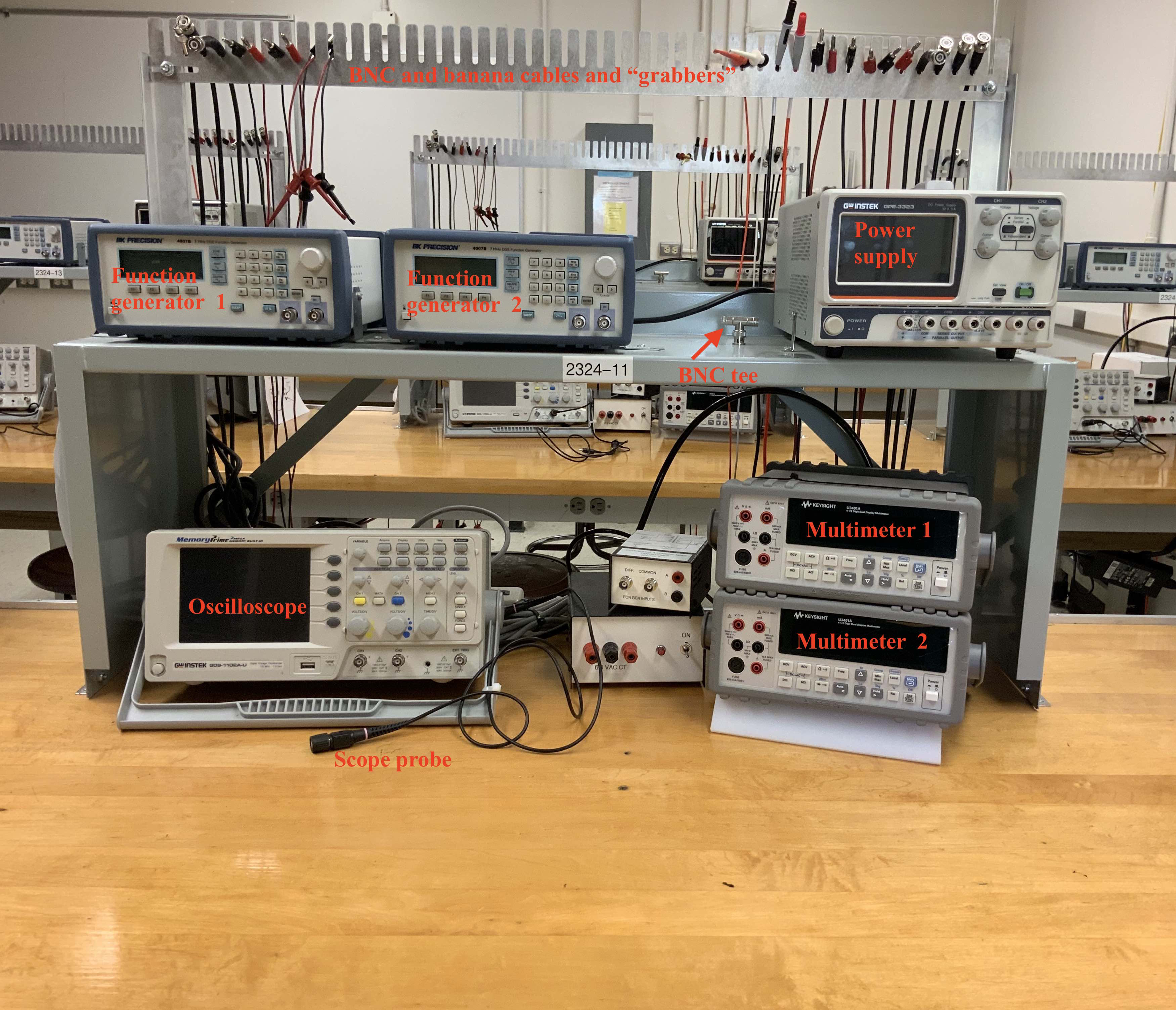
You have two function generators; two multimeters; one power supply, which has three separate power sources; an oscilloscope and a probe for it; a rack behind the station with all the cables you need; and a BNC tee. Spend a minute finding each of these.
At the back of Broida 2316 is a shelf with all the electronic components that you will need throughout the quarter. As you are working on your labs, you will go back there to find what you need. When you are finished with the components you should put them back in the appropriate drawer where you found them. But, make sure to put them in the correct drawer or the next student may get an incorrect component when they take it out of the drawer. Since you may be the one getting an improperly returned component, you should check that what you take out is what you meant to get.
So, go get a 1000 ohm resistor. The drawer will probably just be labeled as "1kΩ" or maybe just "1k", since that is a common shorthand, with the unit implied. When you take it out of the drawer, how can you be sure it is really 1000 ohm, rather than an incorrectly returned component? There are two ways: read the label on it and measure it.
Reading resistor color codes
The 1k resistor should look like this.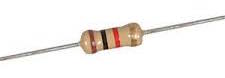
The first three colored bands (brown, black, red) indicate the resistance, and the last band indicates the tolerance, i.e., how much the actual resistance will vary from the specified value. We have a cheat sheet for this posted on the shelves, and reproduced below.
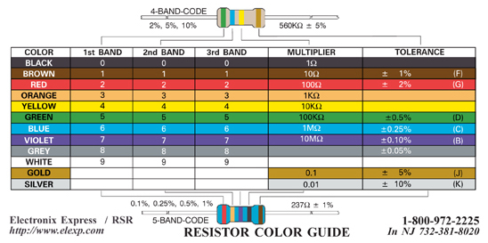
The 1k resistor has bands that are brown-black-red. From the chart, the first two correspond to 1 and 0, so "10", and the red band indicates the multiplier is 100, so the total resistance is 10 times 100 = 1000 Ω. (It is best to think of the multiplier as 10 raised to the power of 2 where the color red corresponds to 2 as shown in the first column of the chart). If this brief introduction is not sufficiently comfortable, browse around for some background information, such as here.
Now that you have identified the specified value of the resistance, let's measure it with the ohmeter part of the multimeter.
The multimeter
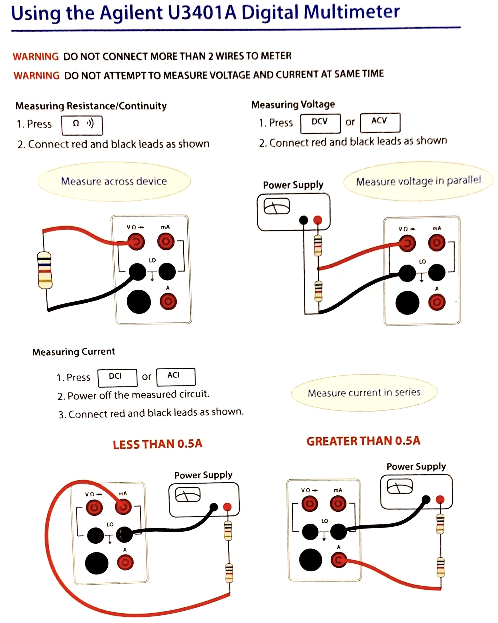
Your lab station has two identical multimeters. They can measure resistance, voltage, and current. You have two because you will often need to measure both voltage and current at the same time.You can find a chart with the connection instructions for the multimeter taped to the end of the lab benches. It is reproduced below.
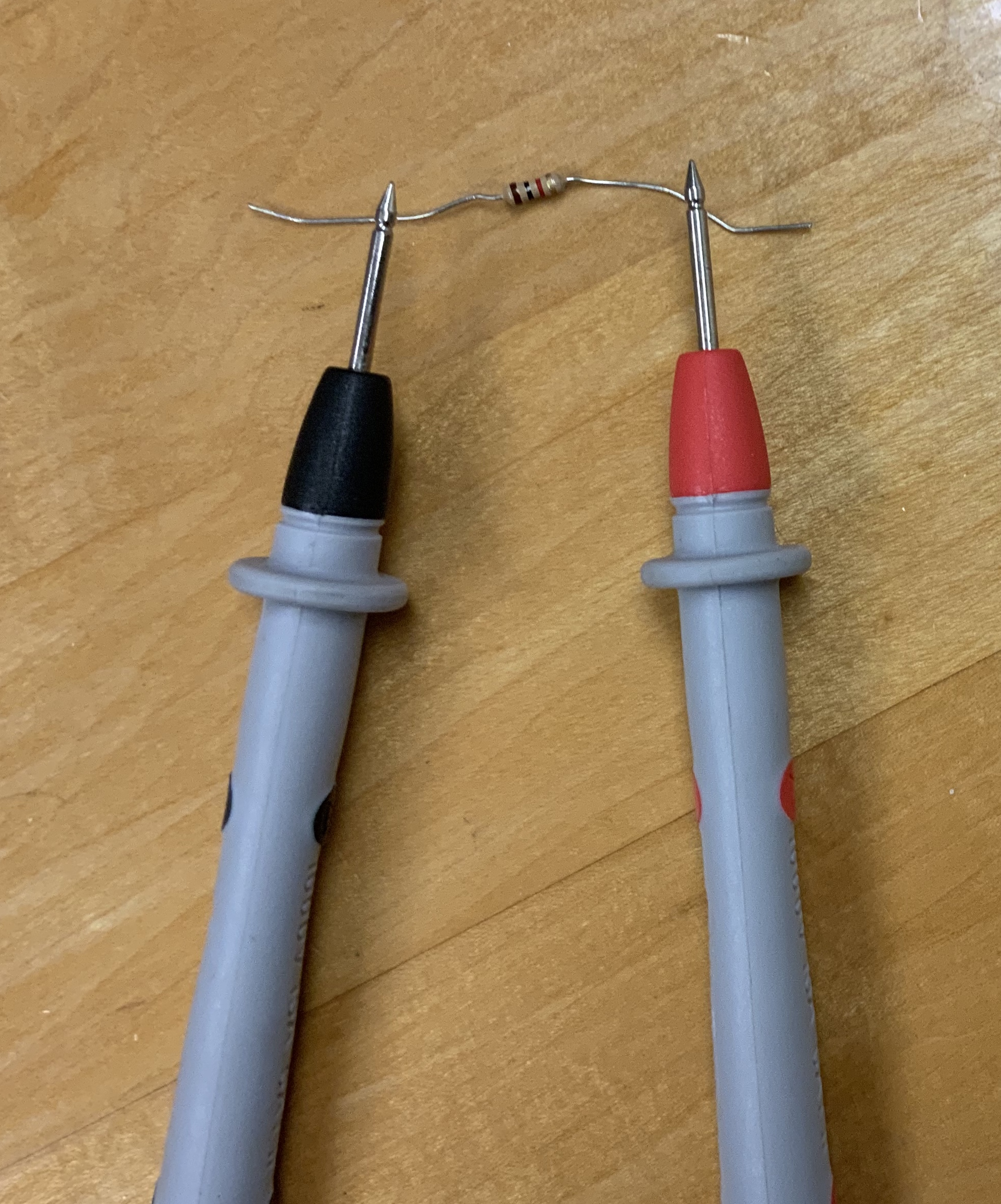
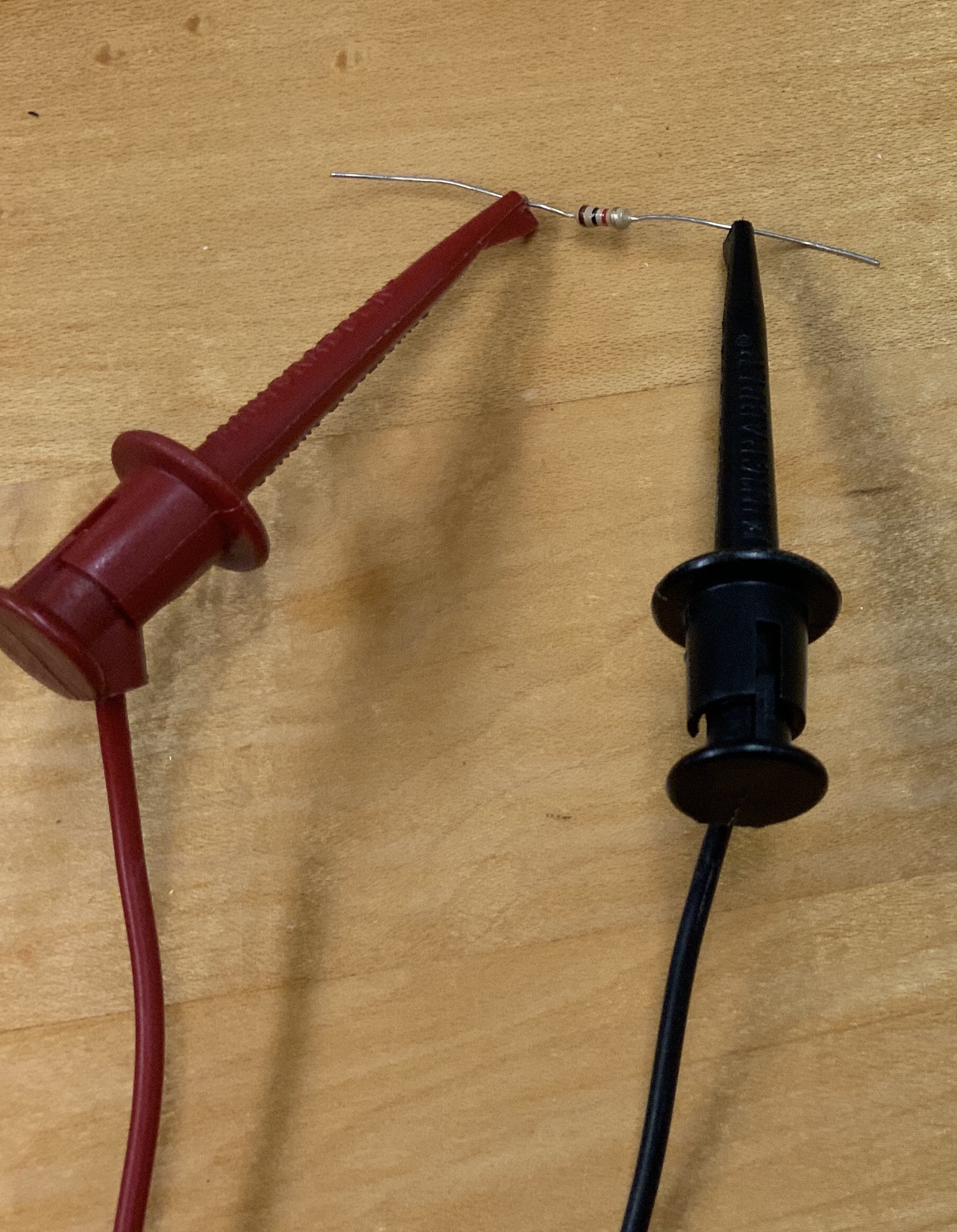
Following this chart, measure the resistance. You will find the cables you need on the rack behind your station. You might be tempted to use the cables that have points at the end, such as shown on the left below. But, it is much better to use "grabbers" like the ones shown on the right. The grabbers will give a more robust connection; try both to see.
Here is what I measured.
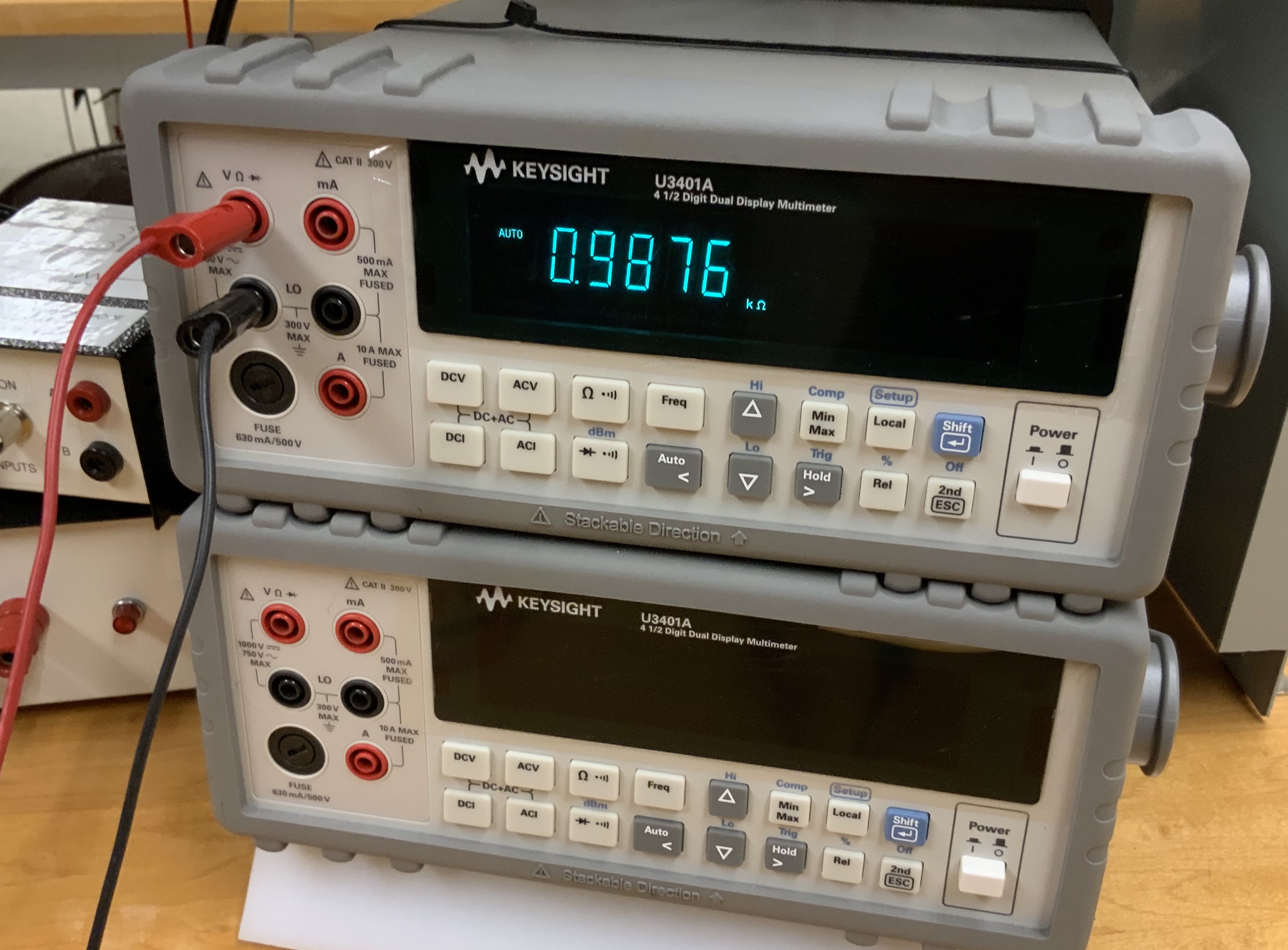
That is pretty close to 1kΩ but not exactly. However, it is close enough. If the circuit called for a 1k resistor, this is just fine! You certainly don't want to keep trying different resistors until you happen to get one that is exactly what is specified. Indeed, for most of what you do in this lab, there is no need for precision better than about 10%. Most circuits are designed to be robust against small differences, so don't worry about precision more than 10% in this lab. That means that you should write this down as 1kΩ without any more precision than that.
However, it is worth writing in your logbook that you measured the resistor to be 1kΩ and you give that resistor a name that you will use in circuit diagrams. Just quickly write something like:
3:50 PM Measure R1 = 1kΩ.You don't need to specify an uncertainty on the measurement. While uncertainties are very important in most lab work, here it is less important for what you will conclude from your work. However, recording and propagating uncertainties is very important in other classes, like Phys128, so don't get out of the habit of specifying uncertainties. Here, though, you should just use the number of significant digits to indicate the uncertainty.
Even without being precise in recording the value you measured, writing down what you measure is important for several reasons. Later on, when you are trying to debug why your circuit doesn't work (and you will definitely have times in this lab where your circuit doesn't work), you may wonder whether that resistor is somehow the wrong value. Maybe you made a mistake in reading the color code or maybe it is just a bad resistor. (For example, another student may have run too much current through it and either fused it to be 0Ω or blown it open to have an infinite resistance. If that happens to you, throw out the resistor. Don't put it back in the drawer!)
Next we are going to use that resistor to play around with Ohm's law as an exercise in using the power supply and breadboard.
Power supply
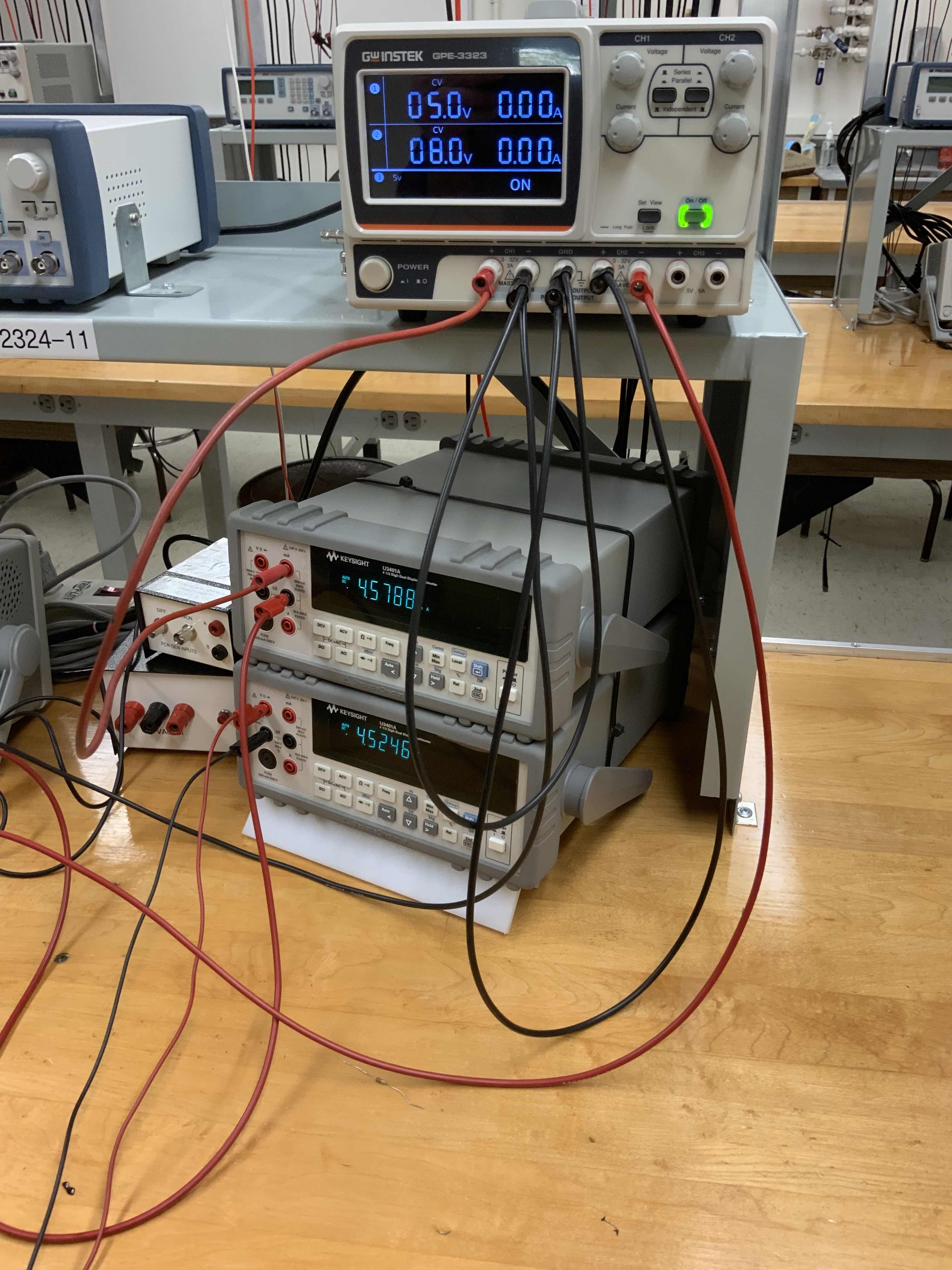
The power supply that you have includes three separate voltage sources. Channels 1 and 2 are adjustable between 0 and 32 volts. Channel 3 is fixed at 5 volts. A picture of the supply is below.
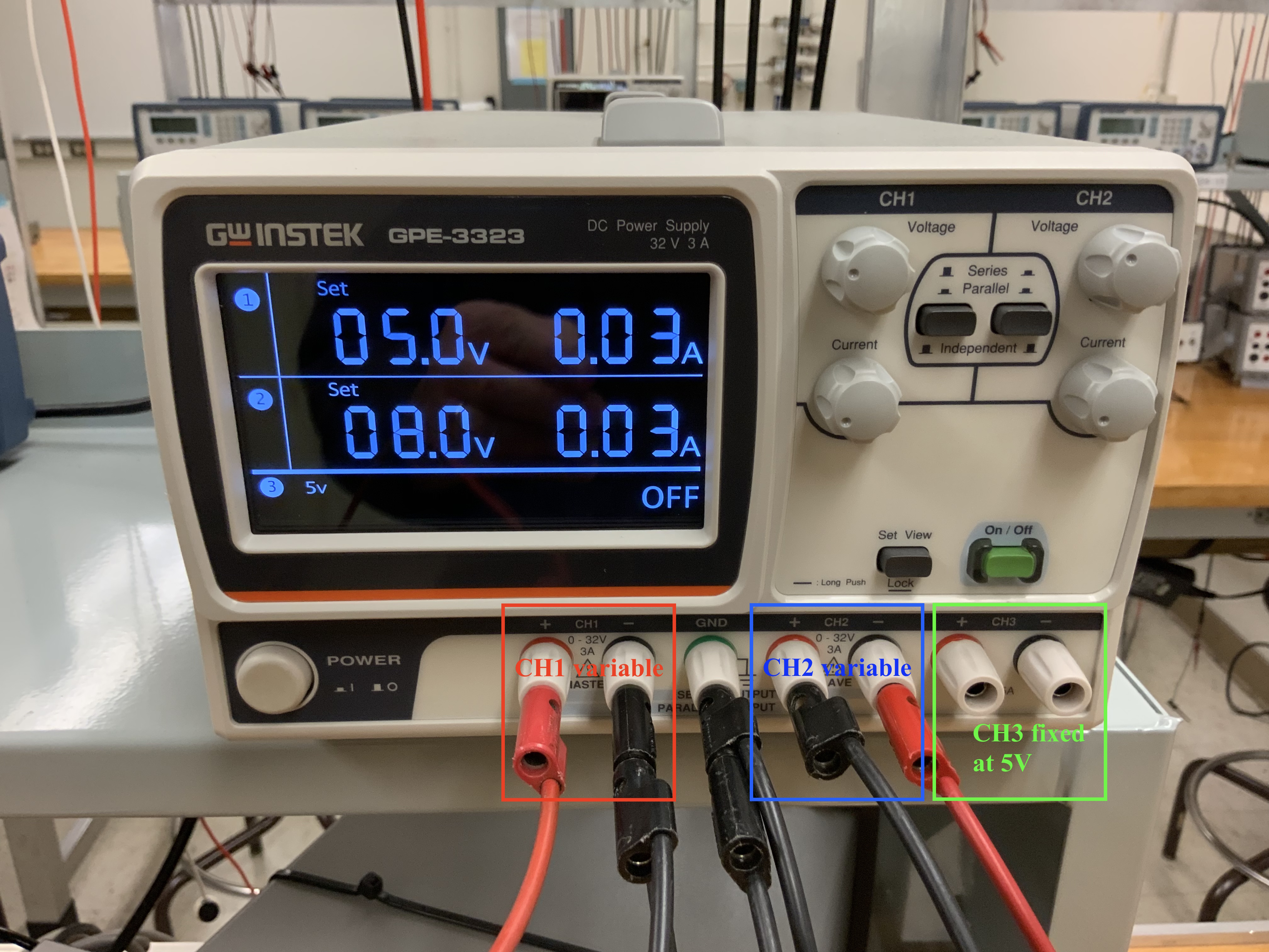
You can configure Channels 1 and 2 to either be independent, in series, or in parallel. Initially, set them to be independent by pushing the two black buttons to be "out".
The output of channel 1 is between the "+" and "-" connectors shown in the red box. The output of channel 2 is between the "+" and "-" connectors shown in the blue box. Similar for channel 3. The "GND" connector is not connected to any of the others. Rather, it is connected to the common ground for the whole room, which we will discuss in class. You should usually choose the "ground" for your circuit to be this potential. So, if you chose CH1 to be +5V and CH2 to be -8V (as setup in the picture above), then the cable connected to the "+" for CH1 is +5V and the cable connected to the "-" for CH1 is 0V. We then connect the "-" of CH1 to the "GND" connector. We also connect the "+" of CH2 to that same "GND" connector so that the "-" of CH2 is 8 V below that ground potential. The way to make that sort of connection with banana cables is shown in the zoomed out view below.

You can adjust the output voltage for CH1 and CH2 with their respective "Voltage" knobs. Set them.
The "Current" knobs adjust the "maximum allowed current" that the supply will output. If you ever connect the power supply to a circuit that tries to draw more than that amount of current, the supply will reduce the voltage until no more than that amount of current is drawn. This is a useful safety feature that will prevent you from blowing out components. You don't want to blow out components! Most of the components you will use in the lab cost at most $1, so there isn't much financial cost in blowing them out. (But, if you work in a research lab you might work with parts costing many thousands of dollars and it is a good habit to learn how to set the power supplies in a safe configuration to avoid damage.) There is a time cost from blowing out components because your circuit will no longer work and it could take you a long time to figure out which component is "fried". So it is worth taking the time to set the max current low. In the two pictures above I have set the "current limits" to different values, 0.03 A for both supplies in one case and 0.2 and 0.1 A in the other. For most of what you will do, a max current of about 0.02 A or so should be fine. If it turns out that you current setting is too low you will know because the voltage shown will be lower than what you set and the supply will have a "CC" indicator (meaning it is supplying a constant current) rather than a "CV" indicator (meaning it is supplying a constant voltage).
Once you have set the supply to be what you want (and made sure that the other end of the banana plugs are not touching each other) you can turn on the supply's output with the "On/Off" button in the bottom right. Until you press that button, and its green light comes on, the power supply is not outputing any voltage. When you turn it on you should see something like the view below.
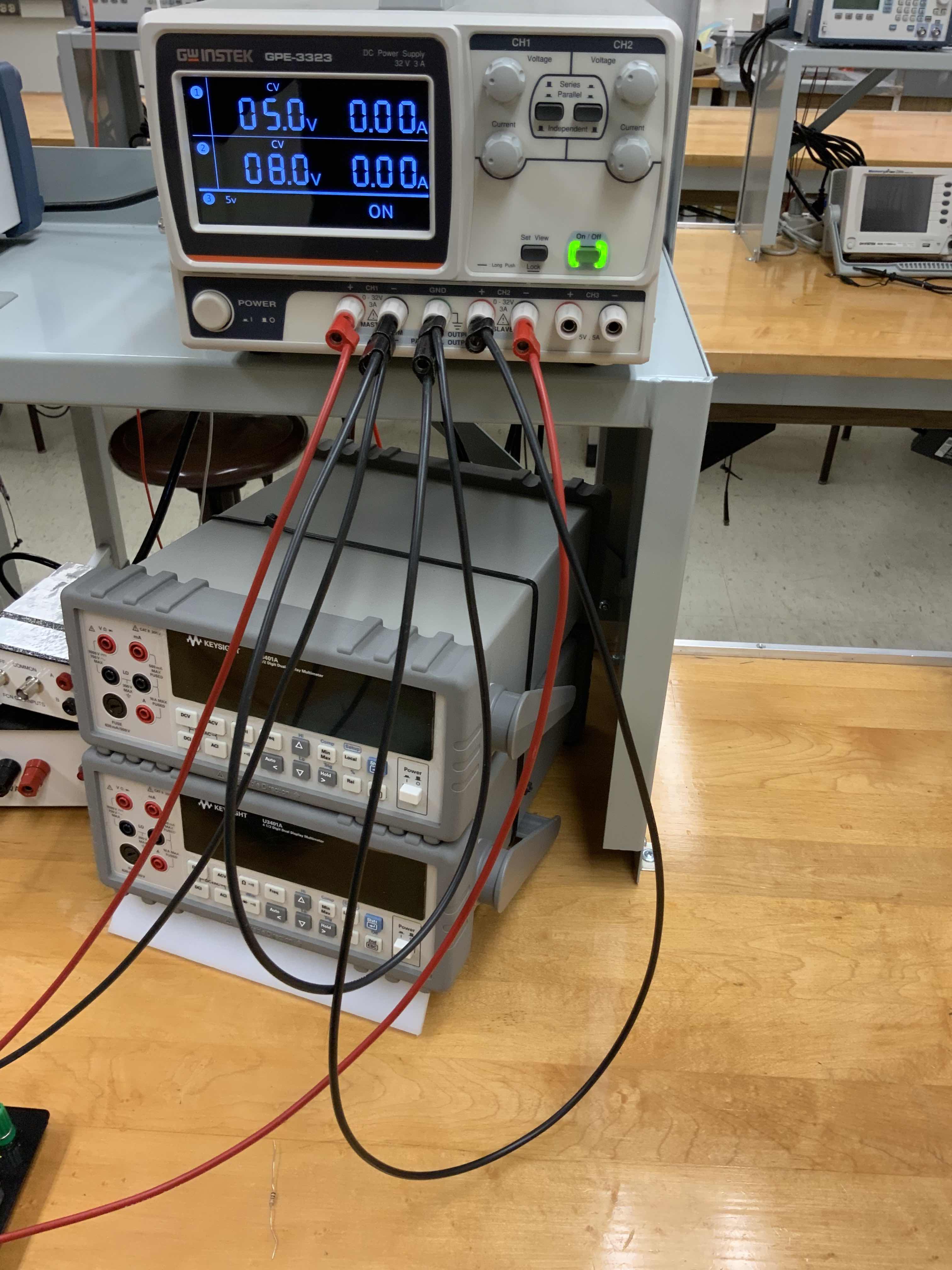
You should see that the voltages shown in the display are the values you specified and the currents are zero. The previous current values shown are the max allowed, but once the supply is on it shows the actual current being supplied.
When you are modifying your circuit, you should turn off the power supply and only turn it back on when everything is ready to be tested. But, use the "On/Off" button on the right hand side, NOT the "Power" button on the left hand side. In general, you will want to leave the "Power" on all the time and only turn the "output" of the supply "On" and "Off".
In later labs, when you build more complicated circuits but find that they don't work, you can ask the TA or LA for help. You'll notice that the first thing they will do is glance at your power supply to see if the green light indicates that it is "On". (Yeah, we all forget to turn things on once in a while.) They will also check whether it is showing "CV" or "CC", where a "CC" means that you either have a short circuit somewhere or just set the max current too low. Get used to making that check yourself. And, while I'm on the subject, the second thing they should ask you is what you did to try to debug it -- learning how to do that yourself is one of the most important take-aways from this class.
Now that you have a power supply, we'll use it to apply a voltage across your 1k resistor. (Note that I dropped the Ω; that is the usual shorthand.)
Breadboard
You should have already read up on how the breadboard works. You should read the preparatory material, such as the textbook chapter, before lab because you will have limited time available in lab! A quick reminder is below:- All the holes in a "+" column are connected to each other
- All the holes in a "-" column are connected to each other
- The separate "+" columns are not connected together.
- The separate "-" columns are not connected together.
- The bulk of the breadboard has rows of five holes that are all connected together but not to any other holes.
You will build your circuits on the bread board. Initially they will be simple, but eventually you will have circuits spanning most of the surface area. The circuits will all need power, and you can use the "+" and "-" columns to provide a nearby "power bus" and "ground bus" for all the circuits. To do that, connect wires between the banana plugs at the top of the board and the "+" and "-" columns. My preference is to make the left hand pair of columns be the positive supply voltage and ground and make the right hand columns be ground and the negative supply voltage. A photo of the wiring necessary to set it up this way is shown below.
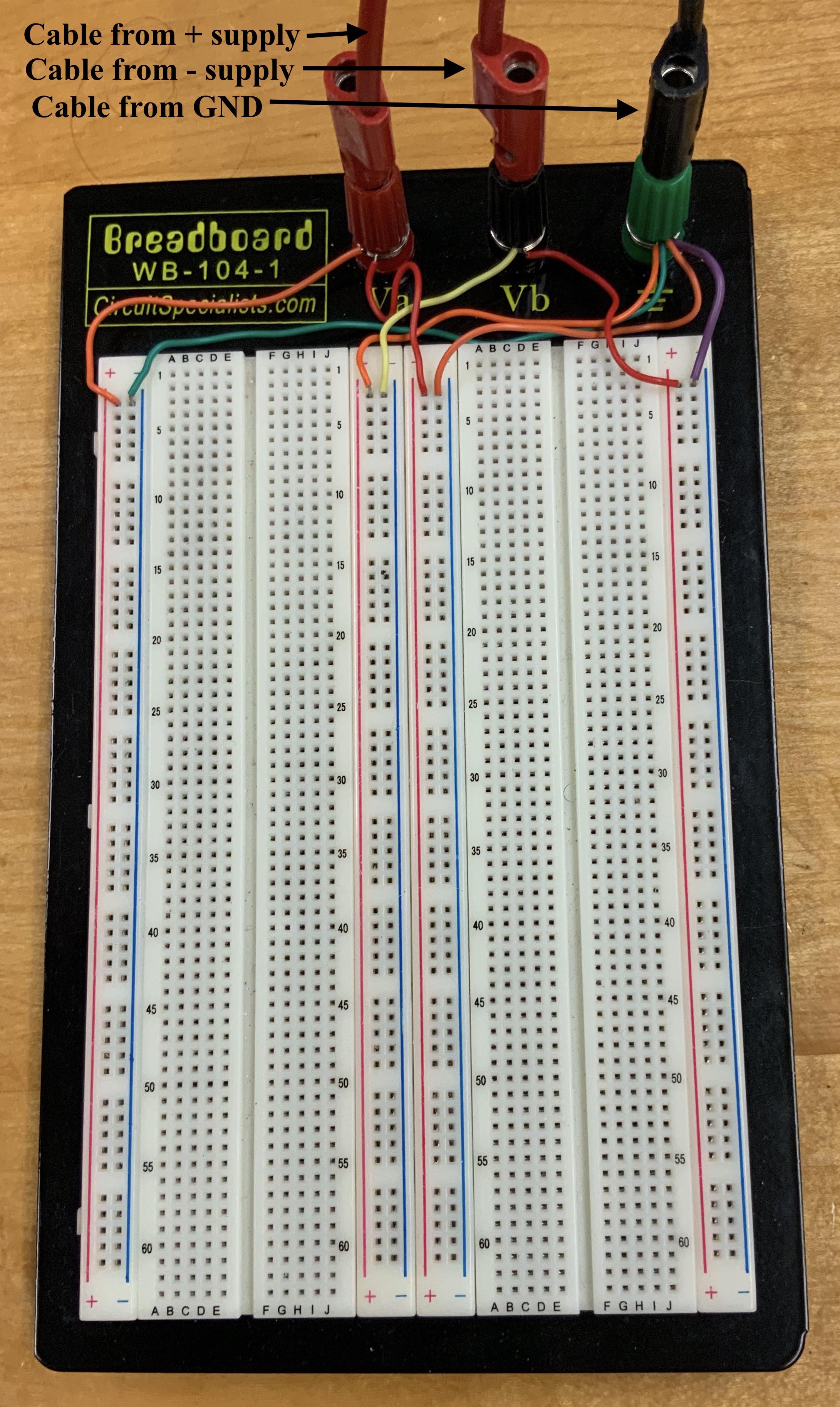
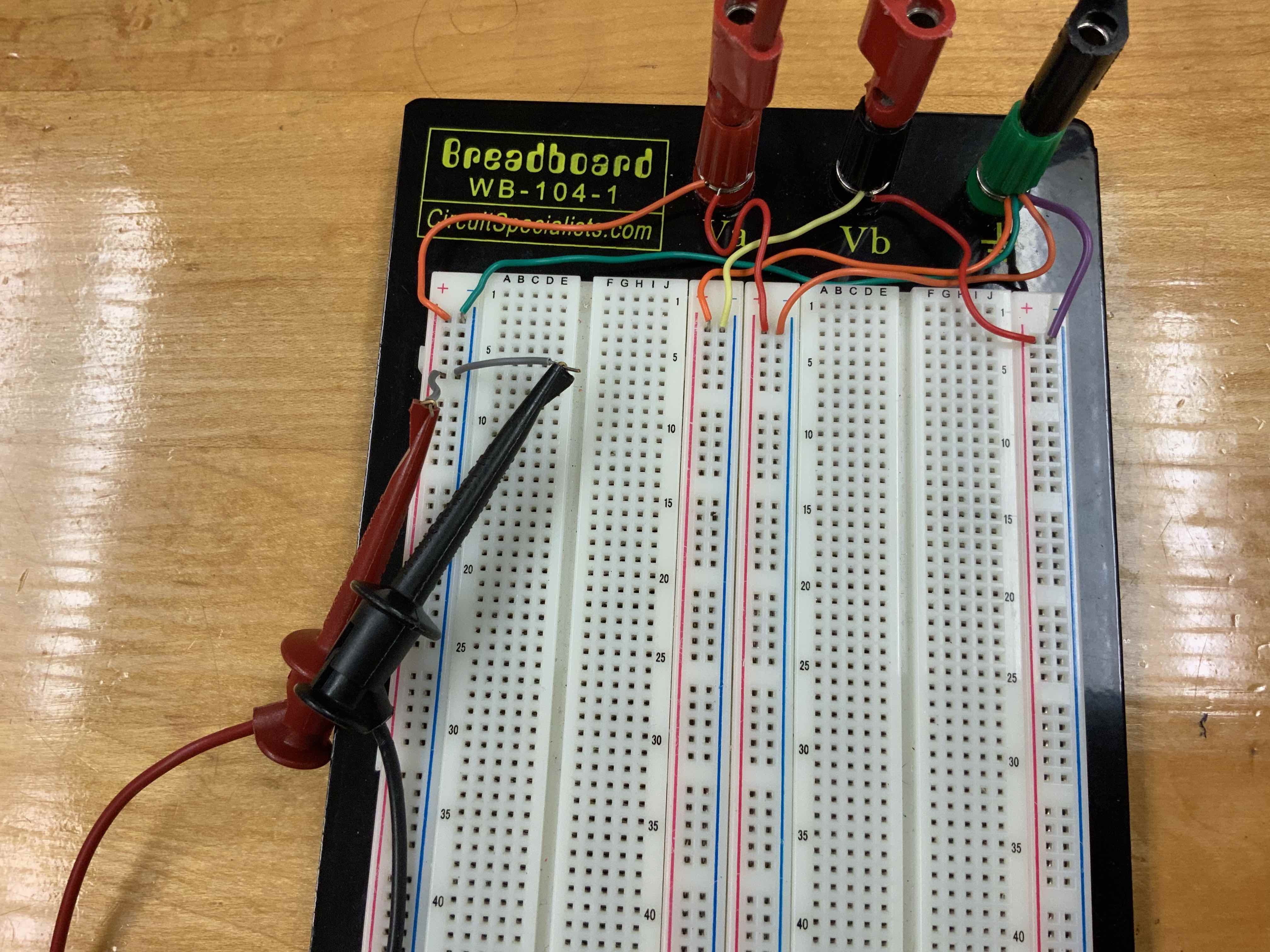
Do this wiring, then use the ohmeter (i.e. the multimeter configured to measure resistance) to make sure that the connections are good. Finally, use the voltmeter (i.e. the multimeter cofigured to measure voltage) to see that voltages are coming through properly. (To make this measurement, use grabbers on small wires that you poke into the breadboard holes, as shown here.) Write down what you measure in your logbook, just to get in the habit of writing everything down. It should only take you a minute to make this measurement (particularly once you get familiar with doing it), but you could waste 30 minutes debugging a circuit that is not functioning because one of these connections came loose.
Checking Ohm's law
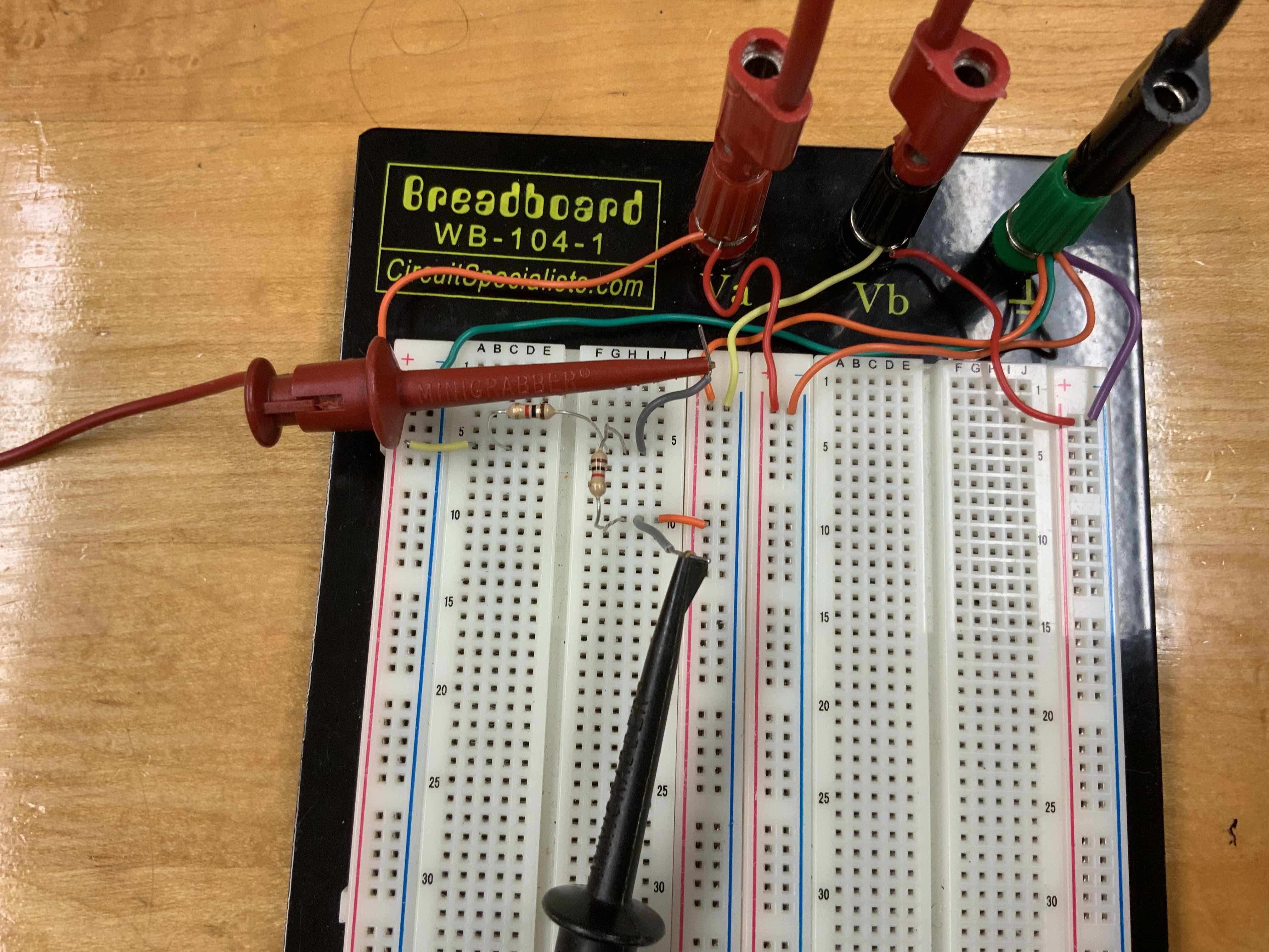
To get practice with the equipment, now you'll put a voltage across the 1k resistor and simultaneously measure the voltage across it and current through it. First, let's just plug in the resistor so that it has the 5 volts from CH1 across it. To do that, place it in the breadboard as shown below.
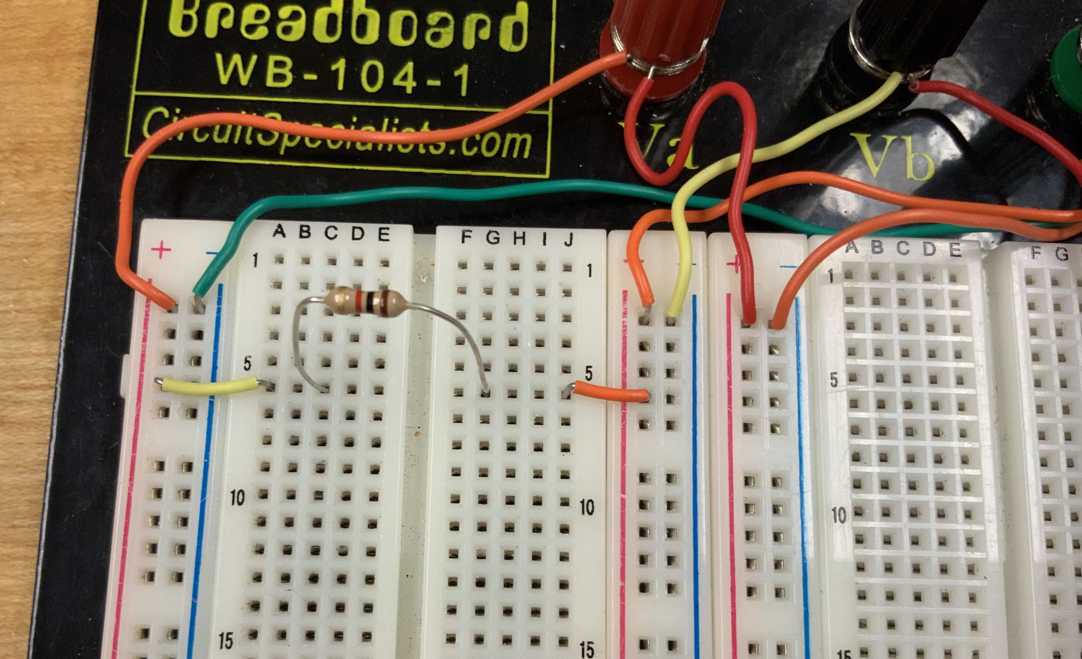
Make sure that you understand why this setup puts that voltage across the resistor. If not, review how the breadboard works or talk with a friend in the class until you feel comfortable with it.
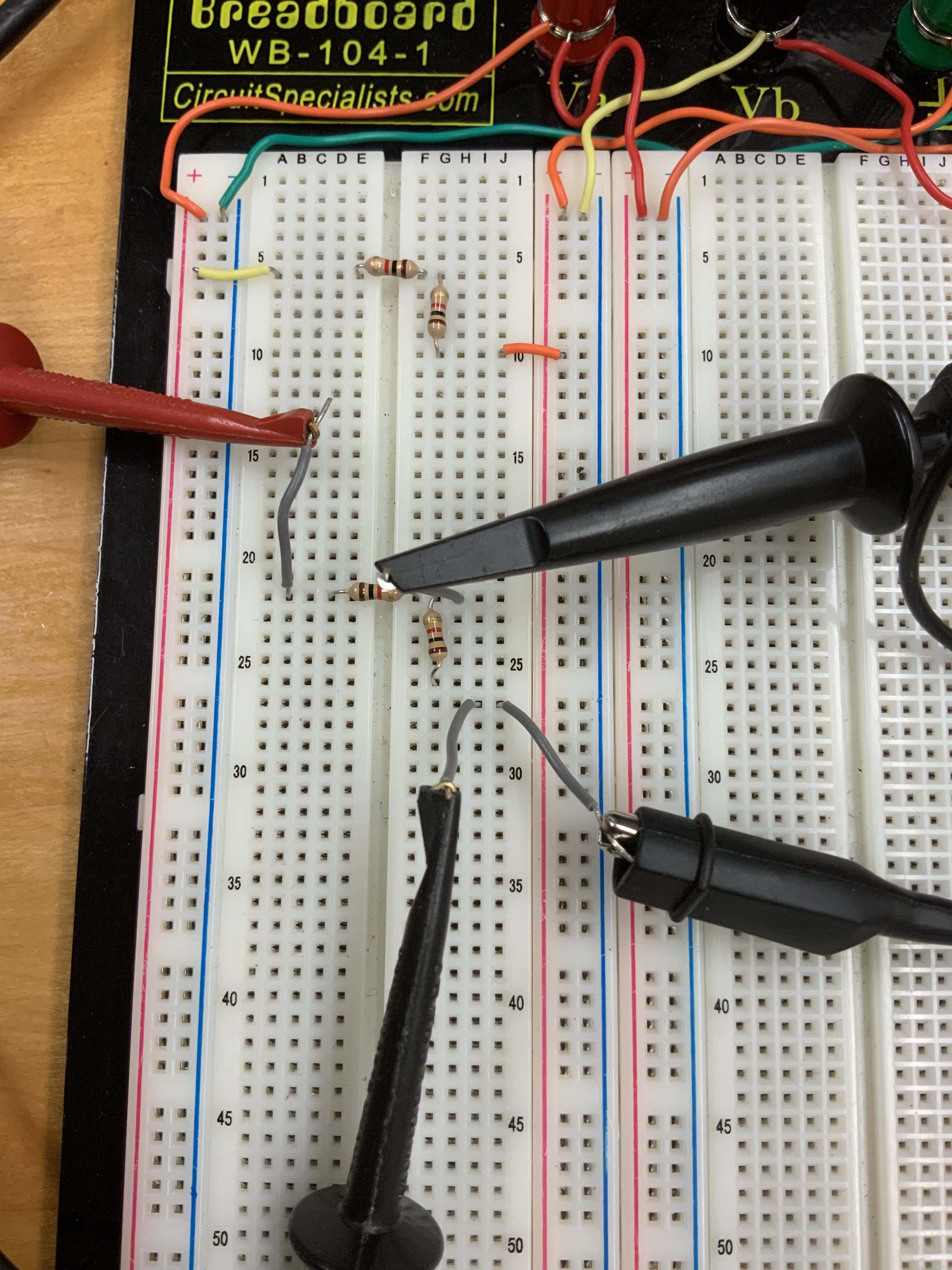
Then, use grabbers to measure the voltage across the resistor as shown below.
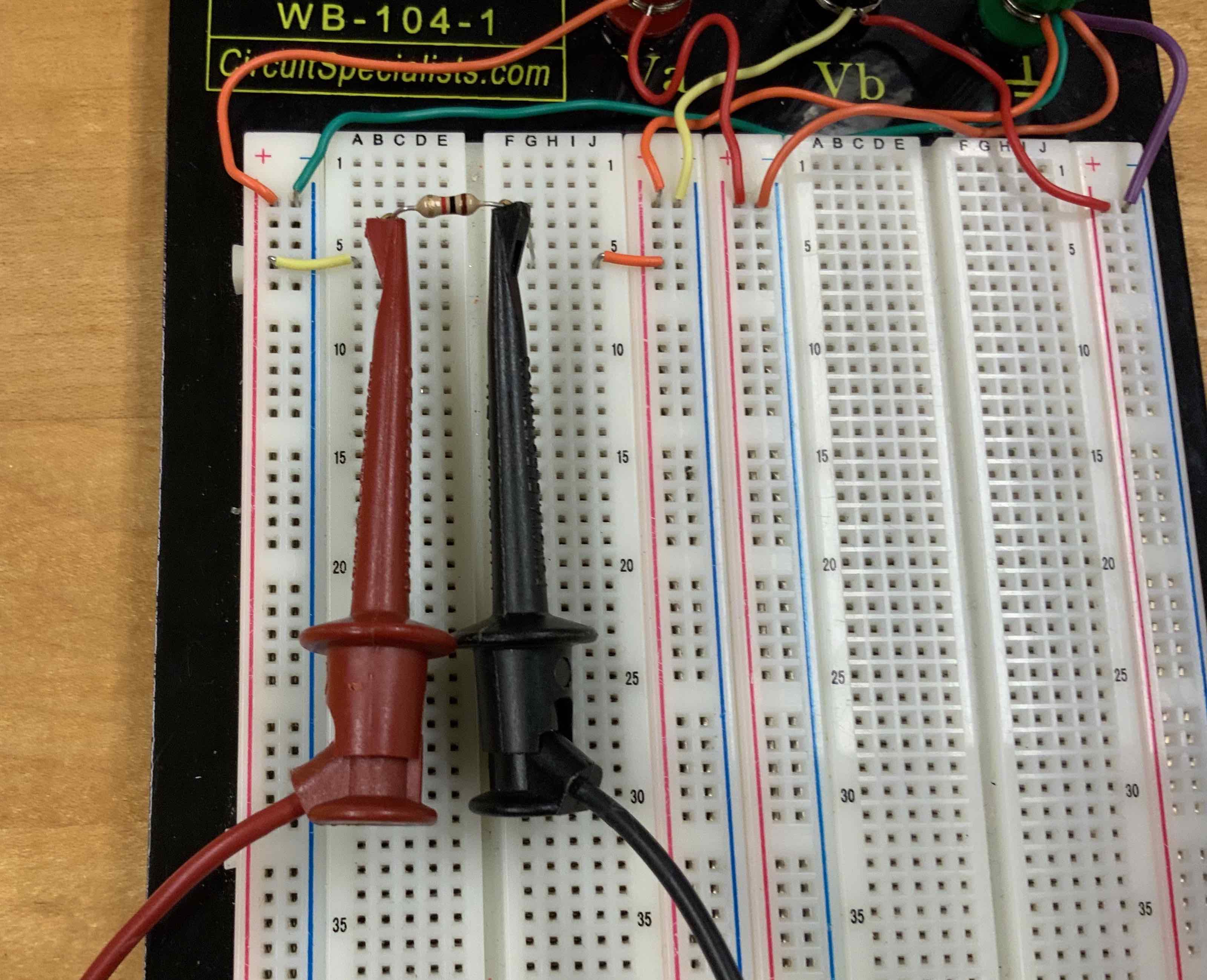
Note, however, that it is much better to not grab onto the resistor's legs because doing that might torque it enough that it comes out of the holes. (Or, when you get more complicated circuits it could move them so that they touch other components and short circuit things.) You will save yourself a lot of frustration by getting in the habit of making measurements with separate wires that you plug into holes near the components you want to test, as shown below.
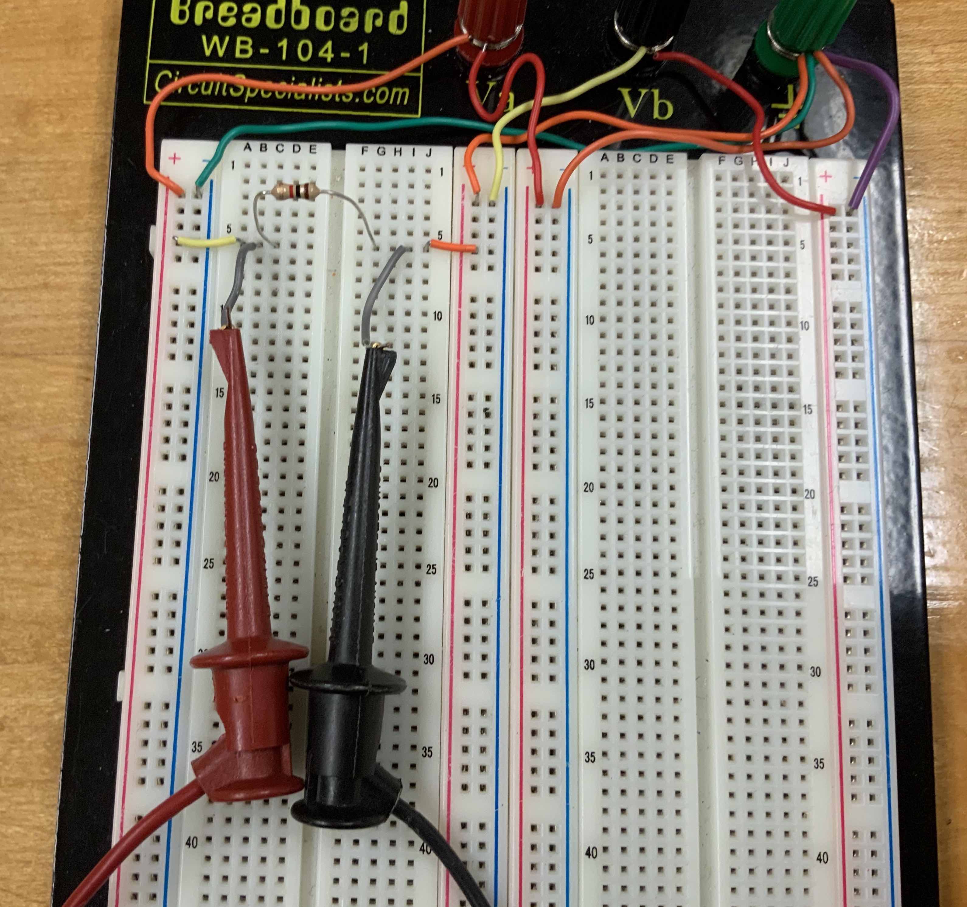
One particularly useful aspect of this measurement approach is that it is sensitive to whether or not the component is properly connected into the hole on the breadboard (maybe you didn't push it in all the way!), while hooking onto the resistor lead won't reveal such a connection problem. This also allows you to make measurements without disturbing the components.
You should measure 5 V across the resistor. Be sure to check that the units are correct. You might find that you measure some small value where the multimeter changes the scale to millivolts (mV). That would happen if you forgot to turn on the power supply. Isn't it zero just because of small round off errors. So, always make sure to check the scale when you make measurements or you might get fooled by a measurement and waste time while debugging a non-functioning circuit.
Again, write down your measurement but don't worry about precision beyond about 10%.
Now, we need to simultaneously measure the current through the resistor while we are measuring the voltage across it. The power supply shows the current being provided, but it probably reads "0.00 A", which just means that it is less than 0.01 A. You need a more precise measurement to see the small current. You can do that with a multimeter, but you cannot measure both voltage and current with the same multimeter, which is why you have two multimeters. If you try to measure current incorrectly, you are likely to blow the fuse in the multimeter. (In fact, you might find that the fuse in your multimeter has already been blown by a previous student!)
If you've never dealt with fuses before, you should read online about how they work. A photo of a good fuse is shown here. The TA can show you some blown fuses; there are a lot of them at the front of the room from previous students mis-cabling the multimeter. (Look for the small gap in the wire.)
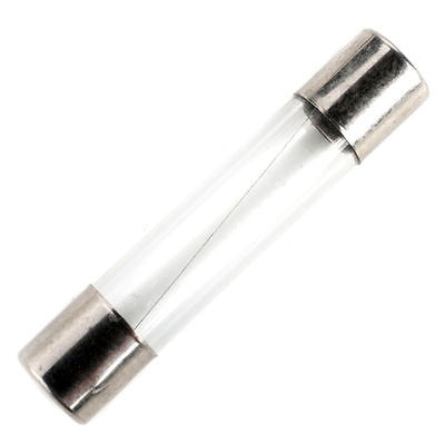
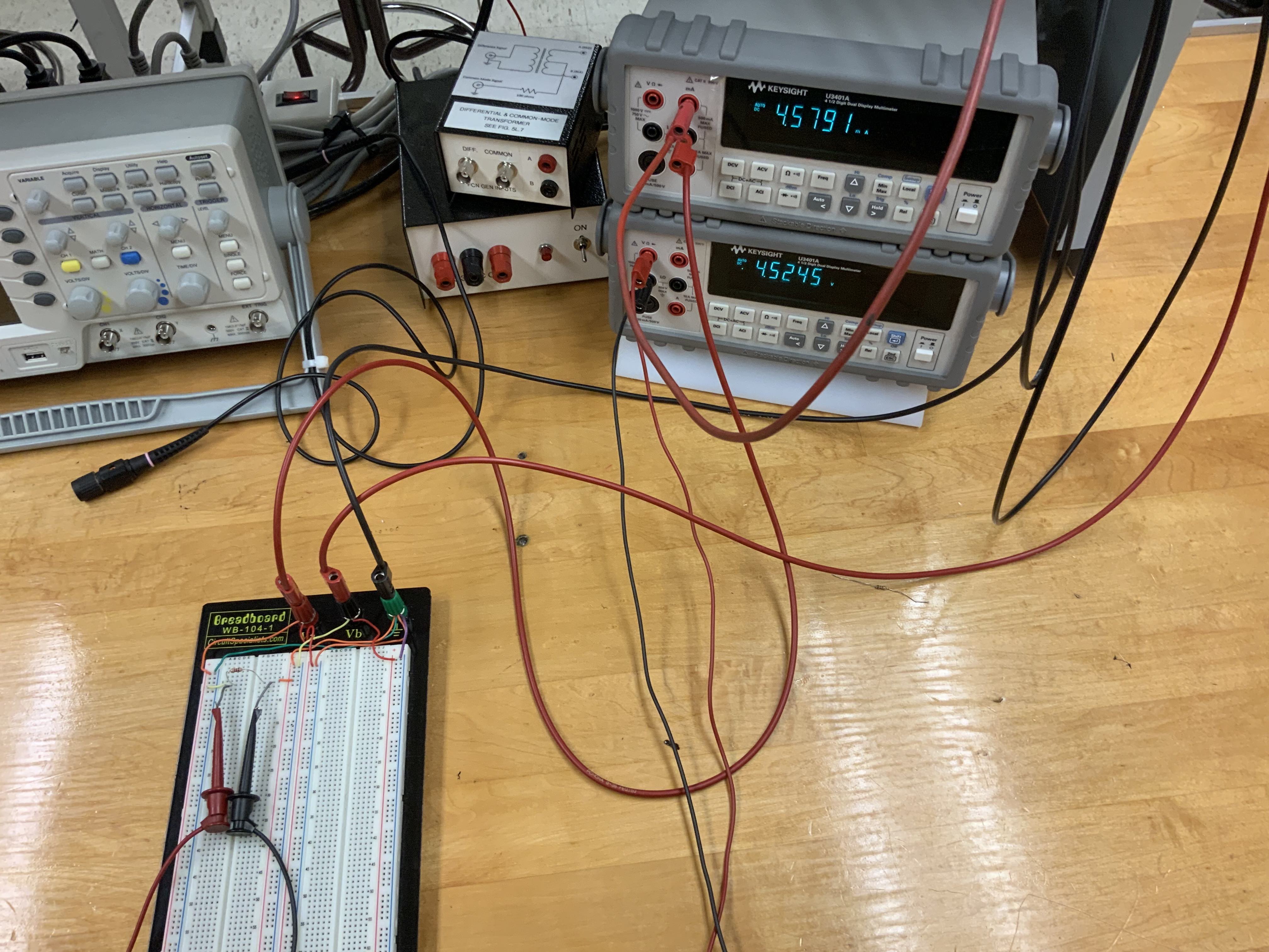
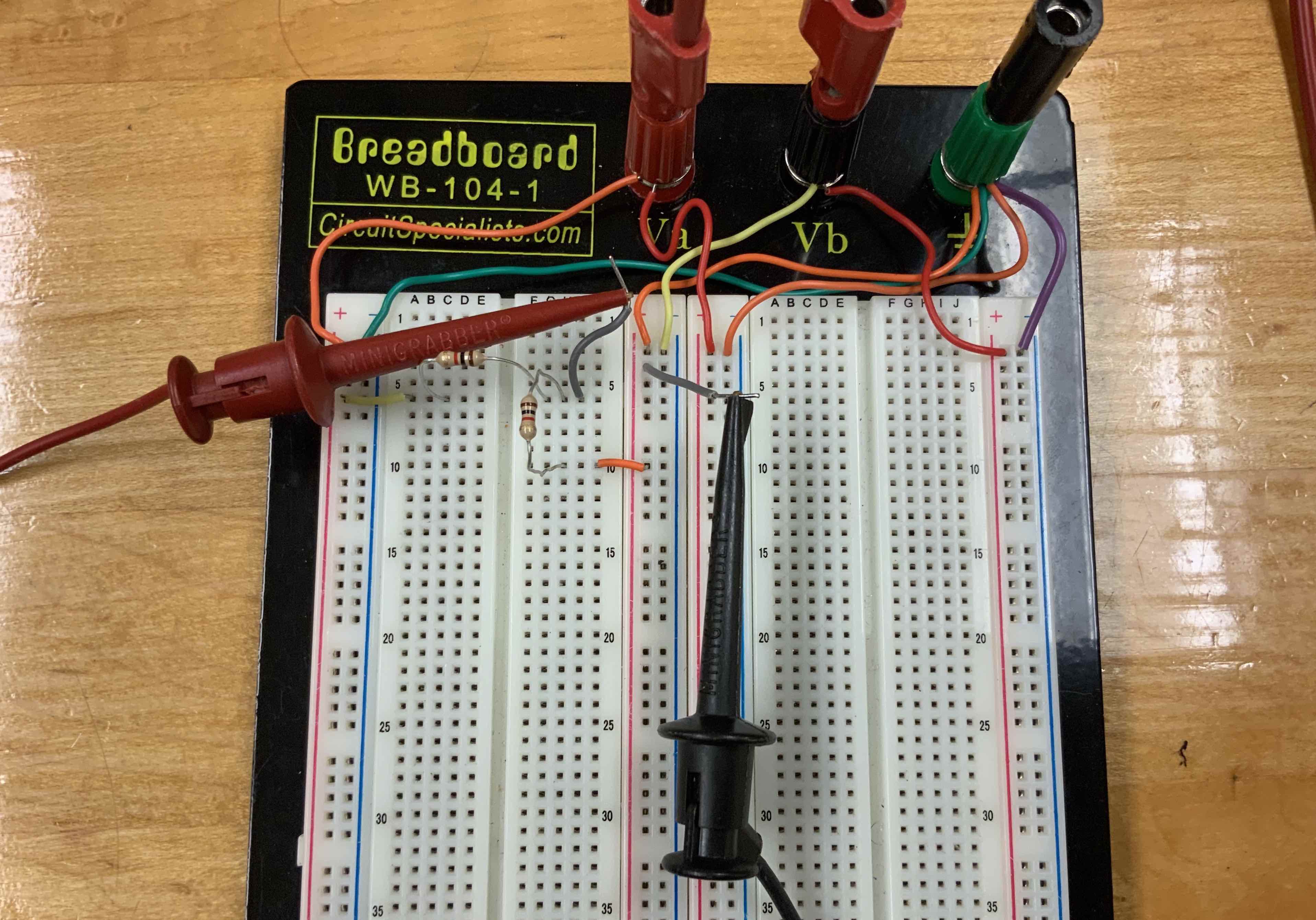
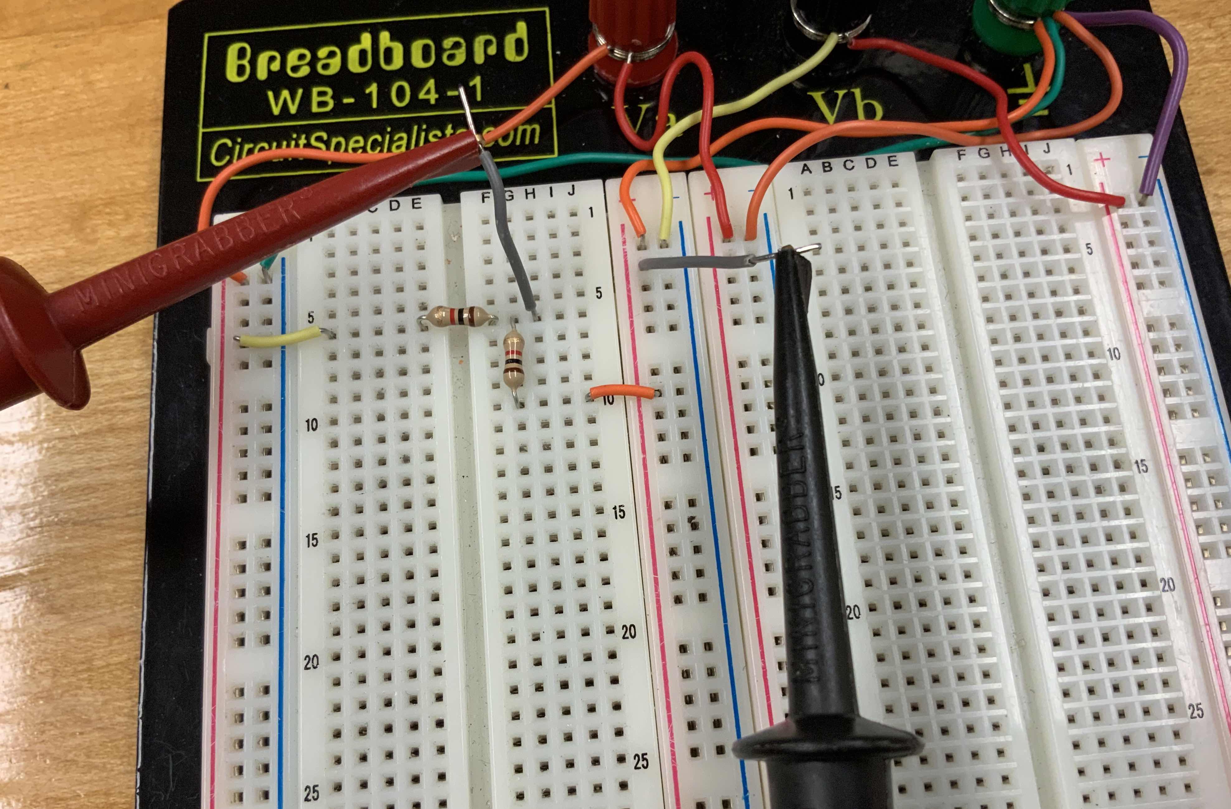
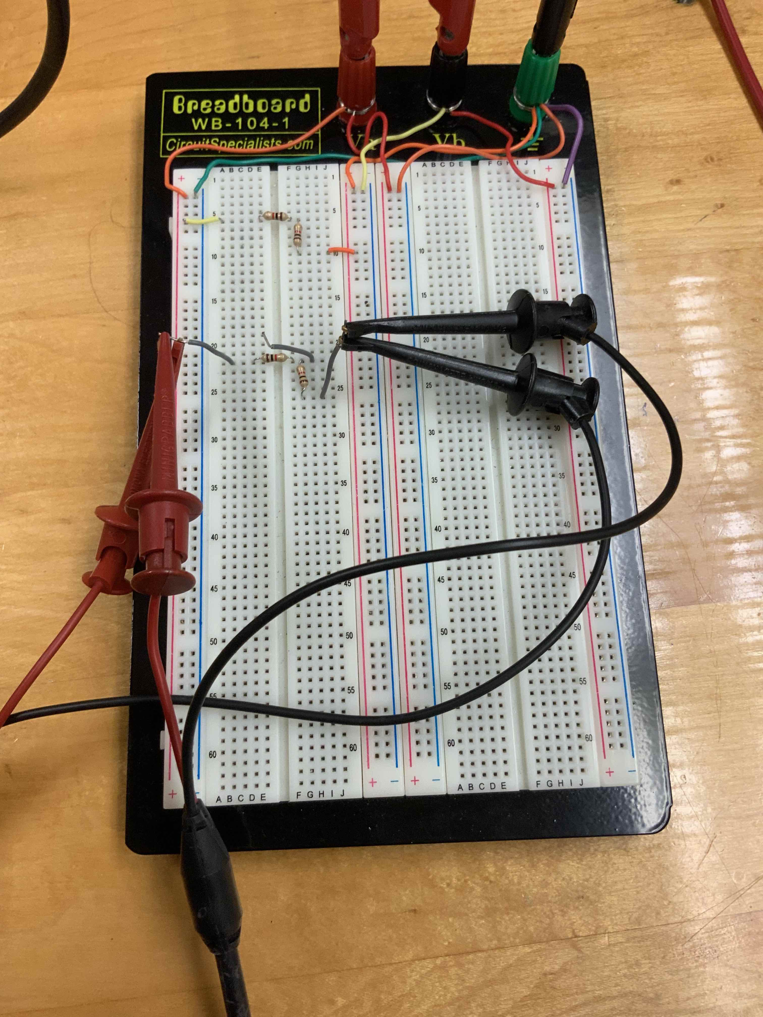
To measure the current through the resistor and the voltage across it, you need to use one multimeter as an ammeter and the other as a voltmeter with the power supply and resistor in a circuit like the one below.
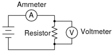
This is done by connecting the power supply to the input of the ammeter (i.e. the mA input of the multimeter with it set to measure DC current using the DCI button.) Then connect the output of the ammeter to the Va connector on your breadboard. This is equivalent to putting the ammeter in series with the power supply connection to your breadboard (as shown in the circuit above). Then use the other multimeter to measure the voltage across the resistor as you already did above. Photos of this setup are shown below (three views with different zooming).
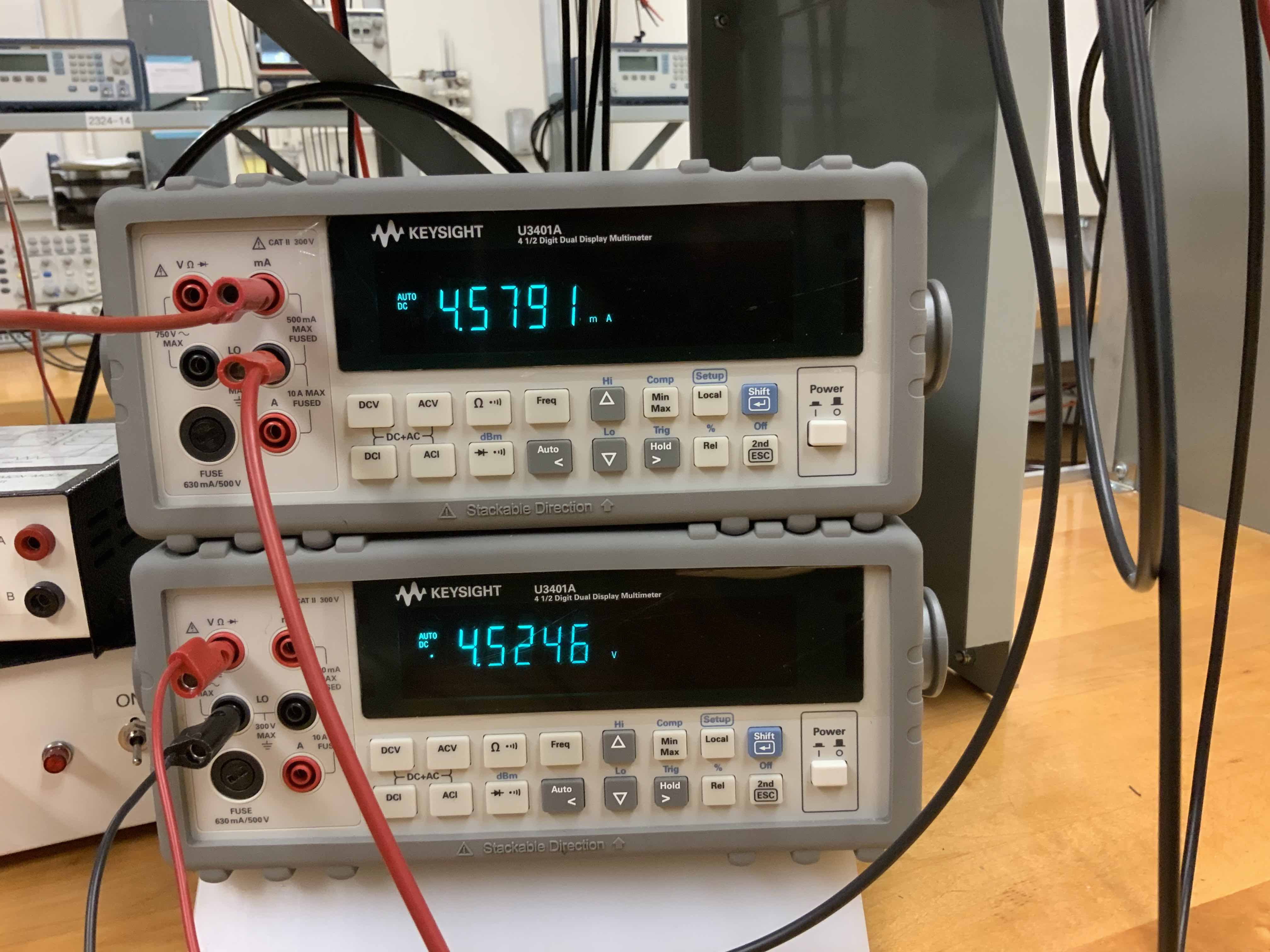
If you measure zero current and see no voltage across the resistor it is probably because the fuse it blown. Ask the TA to check and replace it.
Repeat this for a 10k resistor and then for a 20k resistor to see that Ohm's law applies. Make sure to keep an ongoing record of what you are doing in your logbook.
Make a voltage divider
Next, make a voltage divider on your breadboard using two 1k resistors. Then measure the voltage across the lower of the two resistors and confirm that it behaves as expected.You should be familiar enough with the breadboard by now that you don't need help setting this up, but I'll show you anyway partly to pass on some "housekeeping" advice that will help when you setup more complicated circuits later.
First, here is the setup for the voltage divider and measuring the voltage across the lower resistor.
Here is another way to do it.
The only difference between them is that the first one is explicitly measuring the voltage across the resistor while the second one is measuring the voltage at the top of the resistor compared to ground. That happens to be the same thing in this case, but try measuring the voltage across the first resistor vs measuring the voltage at the top of the resistor vs ground to see how this is different.
Next, let's make a cleaner version of the same circuit. Compare the circuit above to the one below.
The difference is that I trimmed the legs on the resistors so that they will sit down on the breadboard rather than "teetering" around above it. This is neater and it makes them less likely to get bumped out of the holes. For a simple circuit like this it isn't very important. When you have dozens of resistors and other components spread across the board, avoiding bumped connections with a neat layout like this will save you time. Otherwise you might find that you get the circuit working and all that is left before you finish is to take some measurements, but then all of a sudden the circuit stops working because a component got bumped out of connection or pushed so that it is touching a different component. It could take quite a while to figure out which one is the source of the problem! Taking the time to make it neat will save you time (and frustration) in the long run. There are wire cutters at the front of the room; ask the TA. You will probably want to keep some trimmed resistors in your breadboard box.
Oscilloscope and function generator
To get familiar with using the oscilloscope and function generator, we will make a copy of this same circuit, but now instead of using the power supply to apply a constant (DC) voltage, we will use the function generator to apply a voltage that varies as some specified function of time. This is called an "AC" voltage source, where "AC" stands for alternating current, as opposed to "DC" meaning direct (or constant) current. Of course, it is the voltage that we are changing but that also changes the current, and history chose the name AC.We will make the same voltage divider circuit, but rather than moving the resistors, just get new ones and set them up in a voltage divider somewhere else on the breadboard. Then instead of connecting it to the power supply and a voltmeter, connect it to the function generator and an oscilloscope. The circuit diagram for this is shown below.
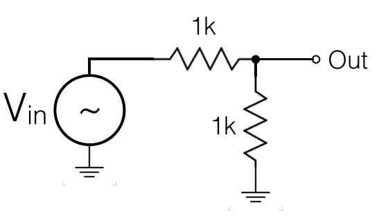
You will use the cables that have a grabber on one end and a "BNC connector" on the other end. (BNC is an acronym for the standard coaxial cables that you will be using.) You can see the grabbers connected to the resistors in the first picture and the BNC connectors attached to the function generator and oscilloscope in the other pictures.
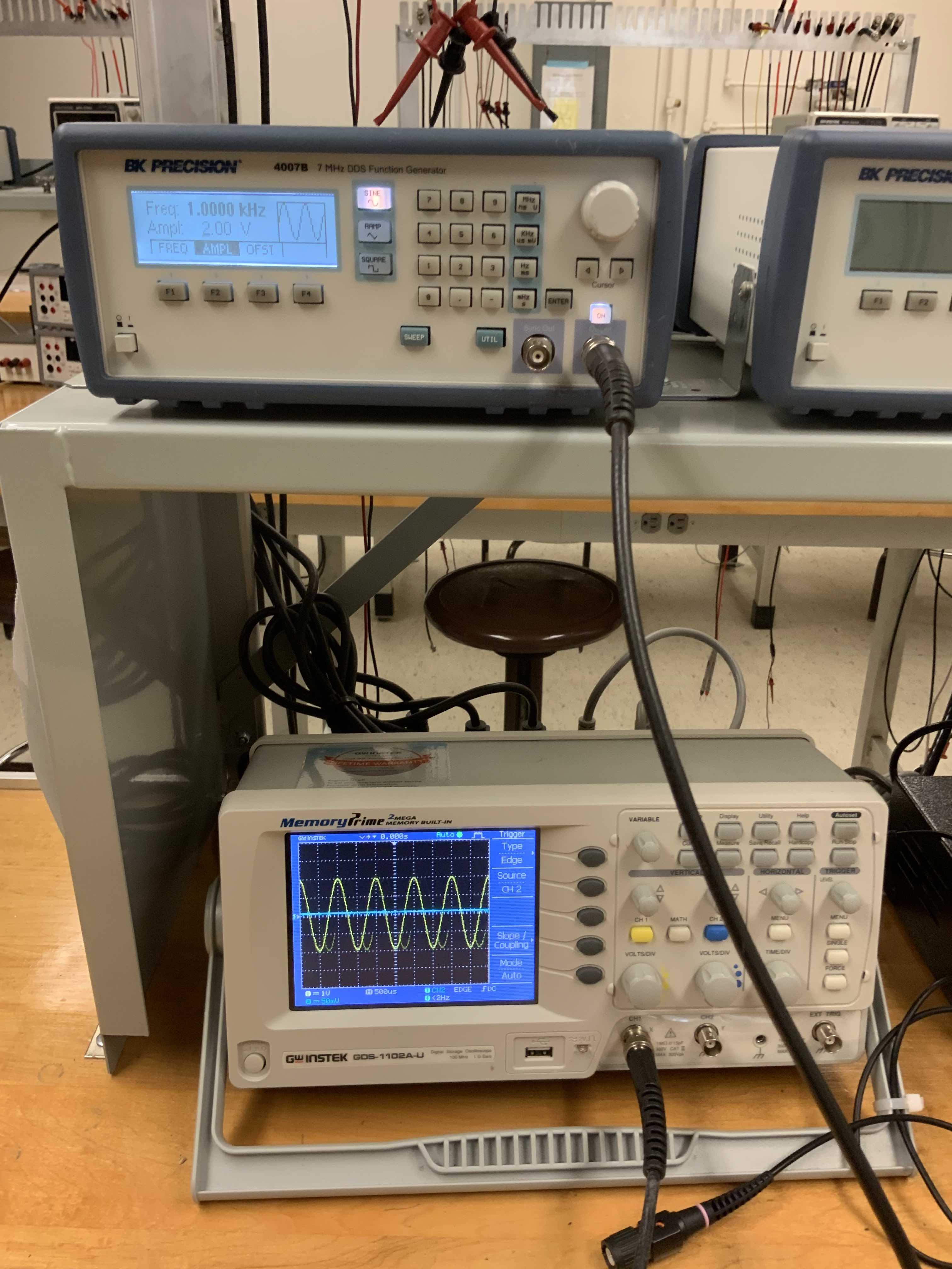
Note that there are two outputs for the function generator. The one labeled "sync out" will be used later; now you just want the one labeled "Output". Also notice that the function generator has a "Power" button and an "On" button. The power button turns on the device and lets you configure it, but the signal is only sent out when the "On" button is pressed and lit.
Also note that the oscilloscope connection is set to measure the full voltage across both resistors in the view above. We'll adjust it later to measure the voltage across the bottom resistor, but for now this shows you what the function generator is putting out. Play around with the settings on the function generator and watch what the signal on the oscilloscope shows. The oscilloscope measures voltage as a function of time and displays it with whatever range you select. (If you are not seeing anything on the oscilloscope, push its "AutoSetup" button, and make sure you remembered to turn the function generator output "On".) You can adjust the oscilloscope's time and voltage scales with the "Volts/div" and "Time/div" knobs. Play around with that until you are comfortable with it. And, adjust the function generator to see all that it can do.
To use the oscilloscope properly, you need to understand how its "trigger" feature works. The oscilloscope (which I will just call "scope" from now on), shows you a snapshot of voltage vs time for a very narrow window of time. To do that, it has to pick which time window to display. It does that by "triggering" the measurement and display on some condition. You can use very specific trigger conditions, which allow you to capture the V(t) behavior for very rare effects. But, you can also just have it automatically trigger on whatever first "change" comes along. You are probably already in "Auto trigger mode". You can tell for sure by looking for the word "Auto" along the top of the scope's screen.
Next, we want to change the scope's triggering from "Auto" to "Normal". Do that by selecting "Menu" in the trigger block on the right side of the scope's control panel. Then you will see "Auto" in the bottom right corner of the screen; click the button next to it to switch it to "Normal". Now, the scope will only trigger when the voltage of a particular channel moves through a particular voltage value. Which channel, and which direction it should be moving (increasing of decreasing), are displayed along the right side of the screen and can be selected with the buttons beside the screen. Set it to be channel 1 (or which ever channel you are using to measure your circuit) and a rising edge. Then use the "Level" knob in the trigger region of the controls to adjust the voltage where the scope will trigger. You should see that the signal passes through that voltage right at the center of the screen. If you want to move the location on the screen where the trigger occus you can use the knob in the horizontal section of the controls. This allows you to view more of what happens before or after the trigger, depending on what you want to see.
The trigger level knob also works in Auto trigger mode, but if you set the level too far away from the range that the signal is covering the scope will just start randomly triggering. That can be useful when you don't know what to look for, but Normal mode is a more controlled way to display things on the scope.
Play around with the scope until you are satisfied that you understand enough of its functionality. You'll want to learn more and more of its features as the course goes on. For example, we'll see later that it can make hardcopies. It can even save an excel file with the voltage vs time for each point on the screen. But, for now you can just use it to view the signals and then make a quick hand sketch of them in your logbook with the time and voltage scales drawn on the sketch.
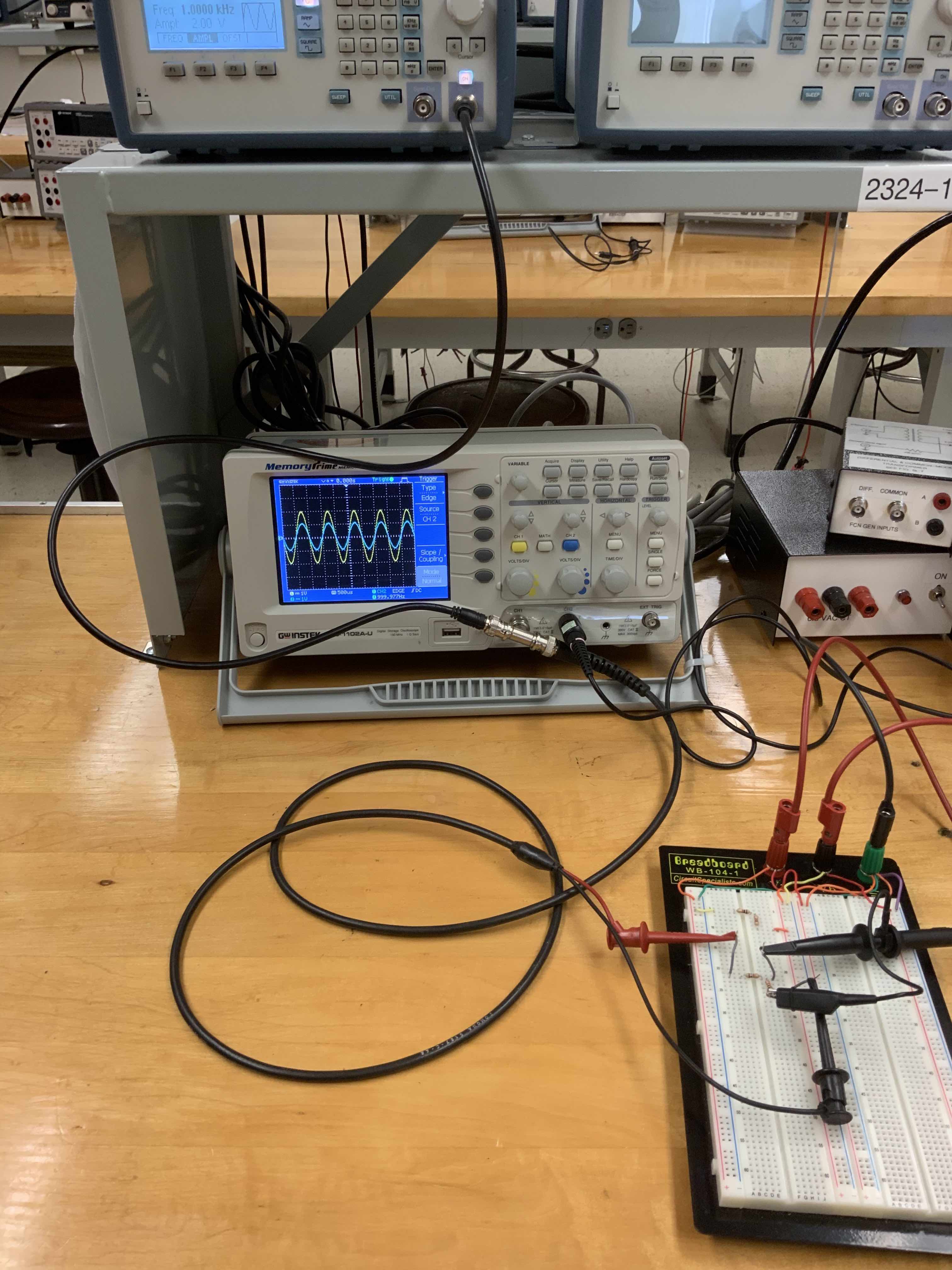
Now, let's measure the output of the voltage divider circuit using channel 2 of the scope. To do that, use the scope probe as shown in the picture below.
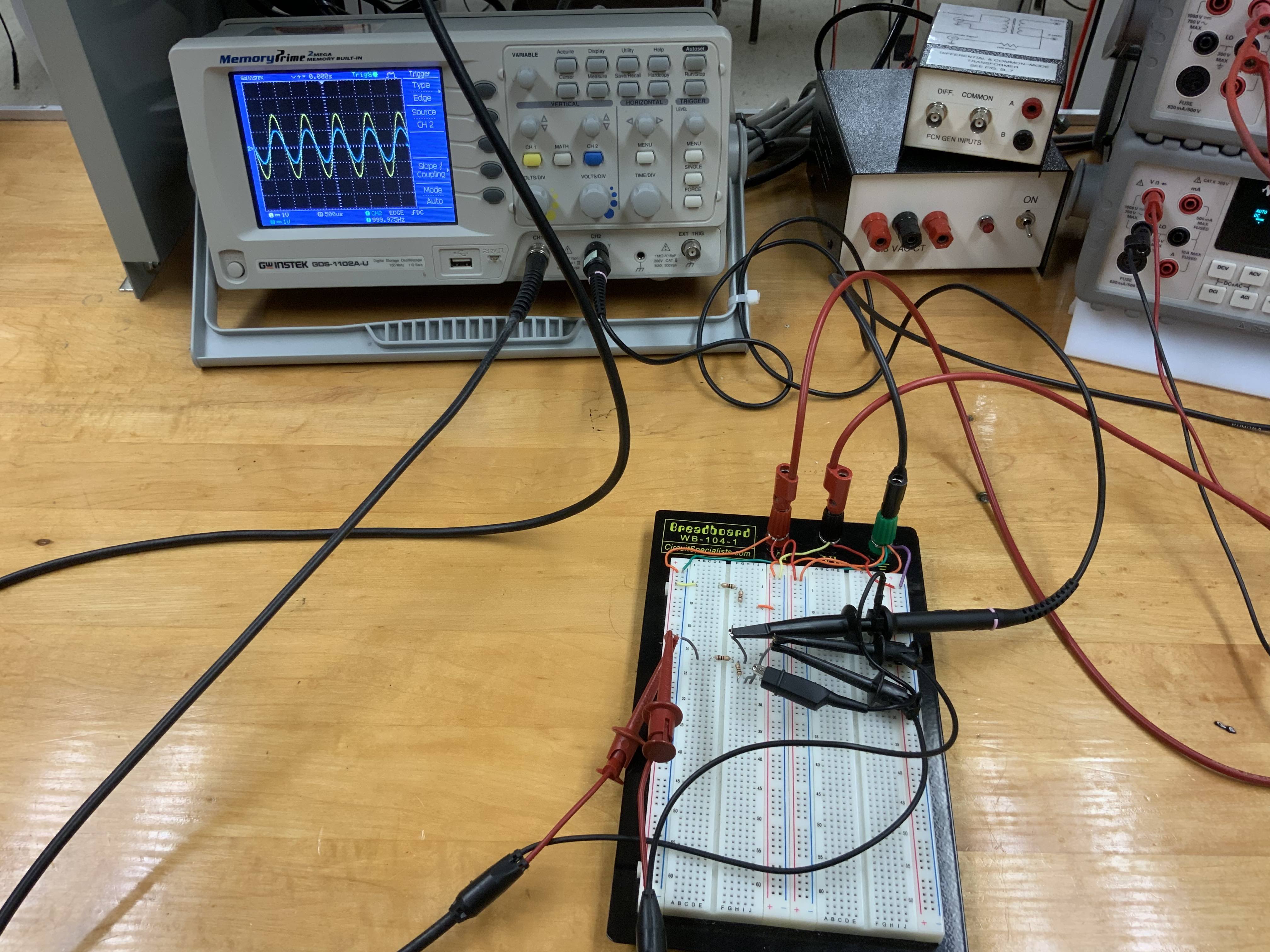
In this picture, CH1 (yellow) is the input and CH2 (blue) is the output of the voltage divider. If one of the two is not displayed it may be that the channel is off. Push the yellow or blue buttons to turn those channels on and off in the display.
Next, use the "BNC tee" instead of grabbers to view the function generator that is input into the circuit. This is a more convenient way, and you should get used to it.
If you happen to have a memory stick, you can try the hardcopy feature. Insert the memory stick and press the "Hardcopy" button to get a screen capture of the oscilloscope. Of course, you can also just take a photo with your phone. Indeed, in addition to making hand sketches of the final result of your circuits, you should take frequent photos. They will help you debug things (and show the TA what the output "used to look like before the circuit broke"). Whenever you take a photo, just write in your logbook:
TIME Photo
That will allow you to correlate the (automatically timestamped) photos saved in your phone with what you were doing at that point in your logbook. And, when you are using an oscilloscope in a research job having those (clean and focussed) photos will help you put together a quick summary of your work to present to your supervisor.
What if the scope doesn't work
Sometimes you will get non-sensical (or even blank) signals from the oscilloscope. Here are a few hints to help debug this.Sometimes the scope probe doesn't connect well. The hood covering the hook on the end can pop off to reveal a small pointed probe. That point is sometimes a better tool than the hook. But, the hood doesn't always reseat properly so the hook is not connected and the scope probe won't give you anything. Usually just pushing the hood in and out a bit will fix this. If you suspect that it is not working, connect the hook to a known signal to make sure you see it. A handy "known signal" that is always available is a 2V square wave signal that is present on the small metal circle sticking out next to the USB port on the scope. Try hooking the scope probe to it and you should see a square wave. (Browse around online for info about how to use this to calibrate the scope probe.)
Sometimes you can't seem to trigger on the signal you want. That may just be that the scope is placed in an unintended trigger mode. Hopefully you understand the trigger features enough that you can go into the menus and check it. But, if all else fails, pressing the AutoSetup button will usually recover. However, don't use this as a crutch to avoid learning how to use the scope -- only use it when a few minutes of effort doesn't pay off.
Sometimes the scope voltage is lower than expected. If so, that could be caused by the fact that the scope has an internal resistance of 1MΩ. For the voltage divider that we built from two 1k resistors, the 1M of the scope is negligible. But, suppose you made the voltage divider from two 1M resistors. What would happen when you connected the scope (and its 1M resistance) to the output?
Usually, when the scope is measuring the wrong thing it is because you set it up to measure the wrong thing. For example, suppose you found that the output of the voltage divider was the same as the input. One simple error that would cause that is that you accidentally set the ground clips to be in the wrong place. In the picture below, the grounds are connected to a breadboard hole that is offset by one from the place where the ground is connected. That is wrong, but the scope will still show you signals because there is a ground connection that comes through the outer shield in the BNC coaxial cable. The scope is properly showing you what is going on in the circuit you built, even if it is not the circuit you meant to build. So make a habit of tracing the connections for the circuit after you build it, and be rigorous in checking that they are all correct. It will save you time and frustration.
Now you will use the equipment to do something that is less of a recipe.
Find the Thevenin equivalent circuit
Find the Thevenin equivalent of the voltage divider circuit you used above. Build that circuit and make sure it behaves as epected.
Measure the IV behavior of a diode
We measured I and V for a few resistor values to see that they are linear as Ohm's law predicts. Now, measure I vs V for a diode, which is a device that does not obey Ohm's law. We will talk about diodes later, for now just think of it as a black box. To get more satisfying feedback from the measurement, use a light emitting diode, which is abbreviated LED. (If you are not sure what an LED is or what it looks like, take this as an opportunity to learn to figure it out yourself with a google search.)If you want an extra challenge, try the following. After you have measured and plotted I vs V by recording some voltage and current values, redo the measurement using the oscilloscope. It can make the measurement and plot it very quickly (in fact, in less than a thousand of a second). As a hint for how to do this, note that the function generator has a triangle wave (or ramp) setting that will vary the voltage that is output as a function of time, and the oscilloscope can provide a measurement of current as a function of time by measuring the voltage across a resistor with a known value.
Conclusion
Make sure to write a conclusion in your logbook. It need not be long, in fact it should not be long. It should be a concise statement of what you did and what you found. You may have been trained in the past that longwinded was better than concise writing. And that probably led you to write about how the lab made you feel and what a wonderful learning experience it was. Don't waste the TA's time writing that BS. And more importantly don't waste your time. The conclusion is there for you!The reason for having a short but clearly stated conclusion is that it will help you organize your work when you are recording your lab work in a research setting. You will often need to go find the part of your logbook when you "measured that thing" and want to be able to quickly say what the result was. You don't want to read a verbose conclusion, or worse have no conclusion written so that you have to wade through everything you wrote throughout the logbook. Instead you want to flip through quickly and find the key conclusion. Then, if you need to find the details supporting that conclusion you read the details in the logbook. This way you can answer a question from your research supervisor in 1 minute by flipping to the conclusion and seeing it right there.
For example, in this lab an appropriately concise conclusion would be
Conclusion
|