Lab3: diode circuits
The goal of this lab is to get familiar with diodes and build a simple DC voltage source using a rectifier.
Outline: Prelab assignment, Limiting current draw, Simple diode circuits, Full-wave bridge rectifier, LED
Prelab assignment
- Read chapter 3 of the textbook.
- Read the caution about limiting current below. Draw the Thevenin equivalent circuit for that results from adding this resistor to the output of the function generator (assume that the function generator has zero output impedance). Calculate the new output impedance of this equivalent circuit, and specify the minimum input impedance preferred for the circuits that you will build using it.
- Analyse the first circuit below and predict the output that would be obtained with an input of a 2 V amplitude sine wave.
Write the answers to items (2) and (3) in a Prelab ELOG entry before your lab period starts.
Limiting current draw
Throughout this lab, you should add a 100 Ohm resistor in series with the function generator, ie with the function generator's output. See photo below.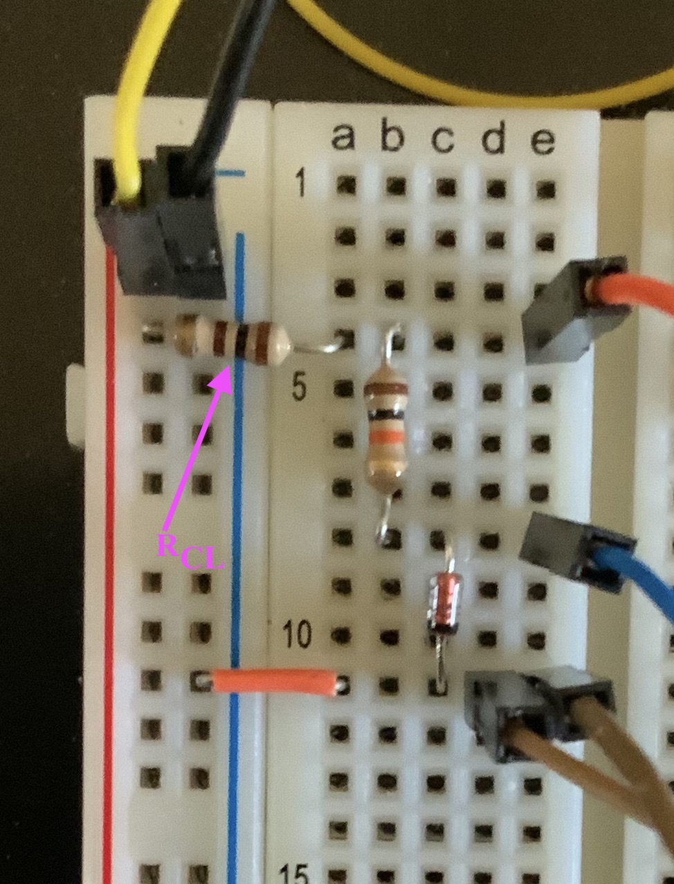
I will label that as RCL to note that it acts as a current limiter (CL) to reduce problems from mis-wiring of the circuit causing a short that might generating high enough current to damage the function generator.
The risk of serious damage is not large, but it is good to be careful and learn about the idea of a current limiting resistor.
Another method to minimize the risk of damage is to turn off the function generator output before changing anything in your circuit. When using the power supplies, you should also turn them off before modifying circuits. Before turning the function generator or power supplies output back on, you should confirm that the circuit is correct and safe by double-checking the schematic for problems and then re-tracing the breadboard layout to make sure that it matches the schematic. Such checks will be quick for the relatively simple circuits you will build in this class, and the consequences of damage are small. However, in real research environments you may use very expensive equipment (>$50k) that you really won't want to break due to carelessness. So, use this lab as an opportunity to build the habit of being careful.
Simple diode circuits
Build the four circuits below and record their behavior with a sine, square, or triangle wave, whichever you prefer.
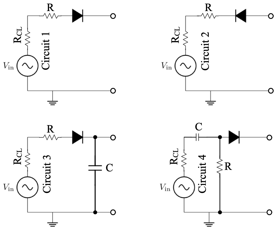
Make sure you understand how the diode is affecting each circuit. Pick values for R and C that you think are appropriate.
Describe in words how circuits 3 and 4 differ. (Hint: without the diode, circuit 4 is a differentiator. What does the diode do in that case?)
Using a diode, build a circuit that will take a square wave input and produce a square wave output with an amplitude limited to no more than one diode drop voltage away from zero in either the positive or negative direction. You don't need to make your circuit limit at exactly ±0.7 V; limiting at something less than ±0.7 V is fine. In fact, you might be surprised that the limit you measure in your diode circuit is less than the nominal 0.7 V diode drop, but note in the IV curve on p81 of the textbook that the diode's IV curve is not a step function at 0.7 V but instead an exponential turn on. What part of your circuit sets the amount by which the maximum voltage of the output square wave is less than the expected 0.7 V? Change your circuit a bit to confirm your expectation.
Full-wave bridge rectifier
In class we talked about using a full-wave bridge rectifier to produce a DC power supply. You could do that using the function generator as the source of the AC sinewave, but the scope makes it hard to probe the output. That problem arises because the scope channels have the same ground, so you can't use them to simultaneously measure the AC input and directly measure the voltage at the output of a full-wave bridge rectifier, i.e., the voltage across RLoad in the diagram below.
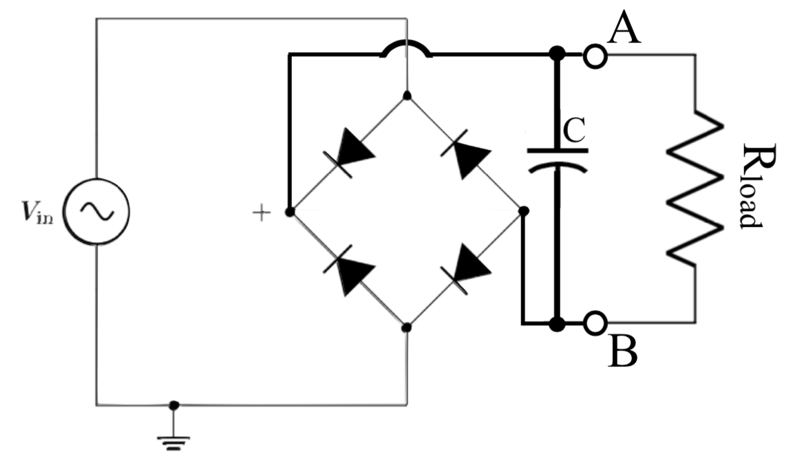
You could measure the voltage at point A (with respect to ground) on CH1 and the voltage at point B (with respect to ground) on CH2, and then subtract the two waveforms. Adding and subtracting the waveforms of different channels is available in the MATH menu. (You could also save the two waveforms as .CSV files and then subtract them and plot the result using software such as Excel, GoogleSheets, or desmos.) Measure the ripple on the output voltage for a load of about 1k and a few different sized capacitor values. Vary the frequency of the input sine wave and watch how the ripple starts to become larger as the frequency gets lower.
LED
Apply a saw-tooth wave across an LED. Remember to keep the 100 ohm RCL in place, and look up online how to tell the proper polarity for the LED. If you drive it with a 3 Vpp signal using a DC offset of 0, you will probably not see any light. But, as you raise the DC offset you will eventually see some light from the LED. That is because the voltage drop for these LEDs is higher than the 0.7 V for typical diodes; indeed an LED's voltage drop is about equal to the energy in eV per photon of the light produced. Looking at the voltage across the LED with the scope, detect the minimum voltage required to get light from a Red, Green, and Blue LED. Those thresholds won't exactly match the energy for those colors, due to other effects, but they will be in the right range.