Lab 6: Operational amplifiers
The goal of this lab is to get familiar with operational amplifier operation.
Outline: Prelab assignment, Power supplies, Using the op-amp DIP in the breadboard, Follower, Observe large gain, Amplifiers, Other op-amp circuit of your choice
Prelab assignment
You will use the LM741 op-amp in lab. Find the datasheet for this part online, save it in your ELOG, and put an image of the pinout in your ELOG. This will help you have easy access to the pinout as you use it.It is generally a good idea to look through the datasheet for circuit elements before using them because the familiarity you get can save time working with it. The simple parts we've used so far haven't needed this, but the more complicated ones we'll use henceforth do.
To get an idea of the cost of these components, look them up on an electronics parts distributor's website. Commonly used distributors are Newark, Digikey, and Arrow.
Power supplies
It is easiest to use dual, i.e., + and -, power suppies for the op-amp. However, there are limitations on the minimum and maximum supply voltages that the part can withstand. Make sure to keep within those limits. (If you need to use an OpenScope due to quarantine, you'll need to get a different op-amp part because the OpenScope cannot provide the ±15 V power that the LM741 uses.)
Put capacitors between each of the power supplies and ground, and situate the capacitors close to where the power is connected to the op-amp. These are called "by-pass capacitors", and they remove high frequency noise. Pickup of radio frequency noise on the power supply lines can cause noise in your circuits, and LC oscillators made from parasitic inductance and capacitance in your circuit connections can cause unintended positive feedback that will generate oscillation noise. These by-pass capacitors short that high frequency noise away to ground and make the circuits "quieter". This is called power supply "filtering" or "bypassing" and can be important when you have a high gain amplifier like an op-amp in your circuit.
As before, it is safest to disable the power while building or modifying your circuit and only connect the power after you have double checked the circuit connections.
Using the op-amp DIP in the breadboard
The op-amp is a multi-pin device that needs more care than the 2- or 3-pin devices you've used so far. It is arranged in a "dual inline package" which is abbreviated as DIP. The usual jargon is to refer to such devices as a "chip", since there is a small fleck of silicon inside with the circuit. The "DIP" refers to the specific package type. To separately connect all pins we need to use the holes on both sides of the breadboard's trench.
The five holes on the left side of the trench are connected together, and the five holes on the right side of the trench are separately connected together. So you should insert the op-amp straddling the trench as shown below.
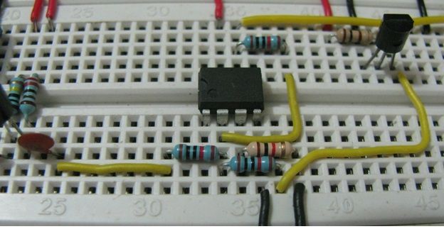
Make sure that it is pushed all the way in. To get it out later, you can insert a small screwdriver or wire in the trench and pry up a bit. Do the prying a bit from one side and then a bit from the other to avoid bending the pins.
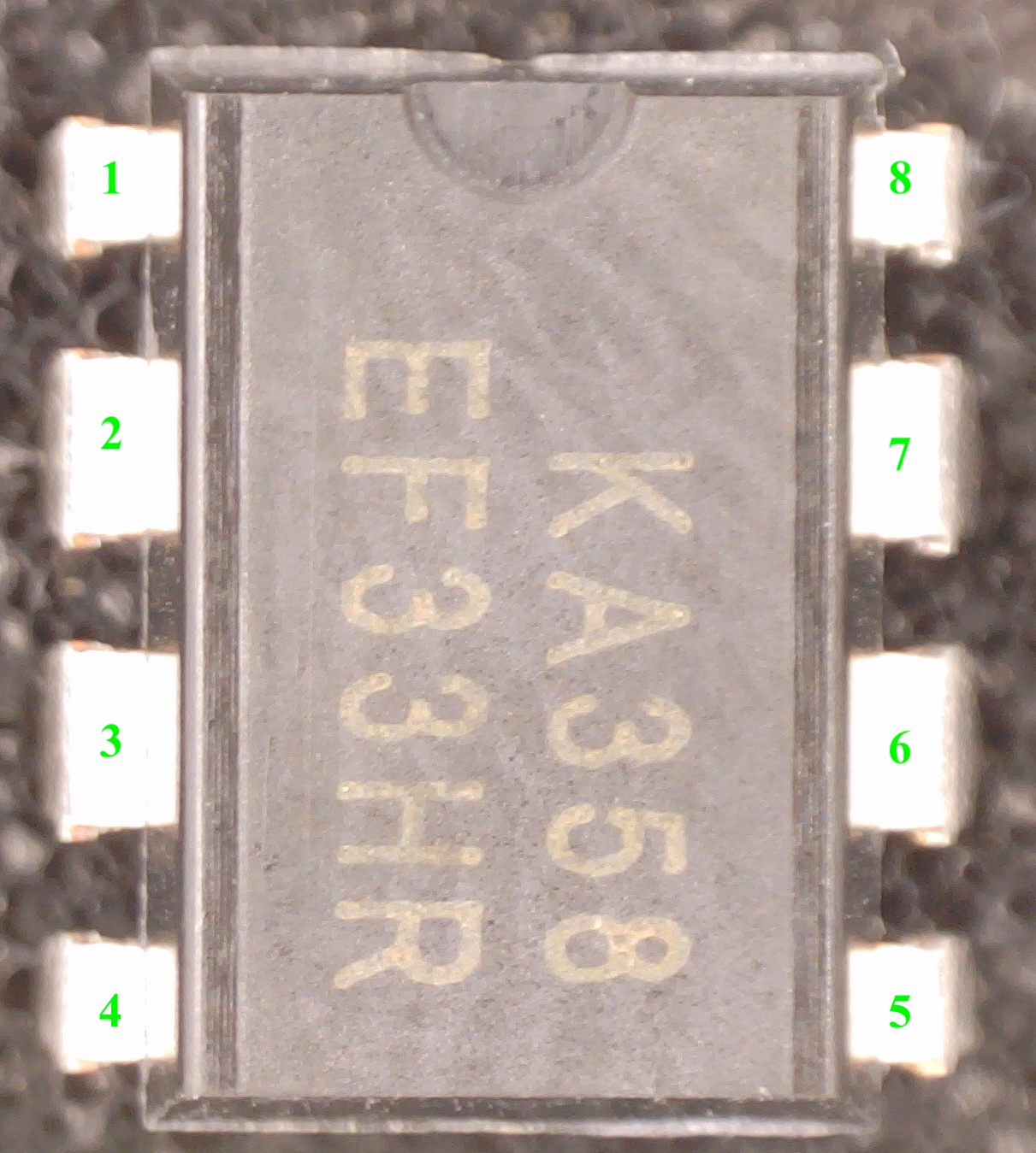
The pin numbers are defined in the datasheet, but it may use a circular mark to indicate the position of pin 1, while our devices use the more standard half circle. The half-circle impression at one edge of the device indicates the "top", with pin 1 at the top left. The pin numbers then increment in counter-clockwise order. This is the standard pin numbering convention for chips. You will also notice that the part number written on the ASIC is oriented to be readable when pin 1 is on the bottom left.
Your op-amp can operate with a single positive power supply for VDD and ground for VSS. However, you can, and should, use a positive VDD and a negative VSS to most easily have positive and negative signal swings.
Observe the large intrinsic gain of the op-amp
The op-amp has enormous internal differential gain so that we can use negative feedback to control the gain to behave as desired. If we don't use feedback from the output to the inverting input, then the output will just enormously amplify the difference between the two inputs. Running an op-amp without feedback is called "running it open-loop", i.e., without a "feedback loop" connection. Observe this enormous gain by grounding the inverting input and feeding into the non-inverting input a 1kHz triangle wave varying from -200 mV to +200 mV. The output will "bang back and forth" between the negative and positive power supply rails.Follower
Build an op-amp follower and make sure it works as expected. Of course getting unity gain from the follower doesn't really alter the signal size, but the advantage of the follower is that it has high input impedance. Verify the high impedance using the same method you used for the emitter-follower in Lab 4. Do that by putting a resistor in series between the function generator and the op-amp input. That resistor and the op-amp's input impedance make a voltage divider so you can measure the input impedance by watching the output signal change as you vary the resistance value. This will actually be hard to do because the input impedance is so high that it will be biased by other parts of your measurement. So, just confirm that the input impedance is at least 1MΩ.You should similarly demonstrate that the output impedance of the op-amp is small using a voltage divider on the output.
Amplifiers
Build a non-inverting amplifier with some reasonably chosen value of gain and verify that it works as expected.
Build an inverting amplifier with some reasonably chosen value of gain and verify that it works as expected.
Marvel at how much simpler it is to do that with an op-amp than with transistors.
Another op-amp circuit of your choice
Build one other op-amp circuit of your choosing, such as an integrator, differentiator, or summing amp.Although not required, you might be interested to look at the "functional block diagram" of the op-amp in its datasheet. It will have many transistors, but you should be able to understand most of what they do by now.