Lab 8: AM Radio
Sat May 16, 2020 12:17
The goal of this lab is to build an AM transmitter and receiver, with an optical interface. It puts together several of the circuit elements you have learned about previously in a more complex, multi-stage circuit.
Outline: Prelab assignment, Circuit overview, Transmitter, Receiver, Going beyond
Prelab assignment
There is no prelab assignment this week.Circuit overview
The overview of the circuit is shown by the following stages.
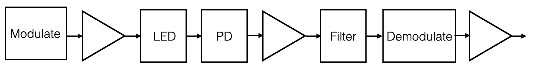
A more complete schematic for the circuit is shown below.
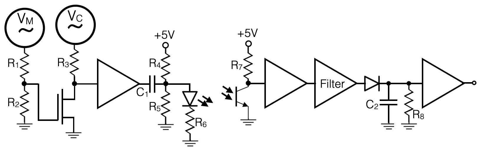
Notice that this is actually made up of two halves; a signal generator and transmission section and then a receiver and demodulation section. It will help if you keep the two halves, and indeed each stage, cleanly separated on your breadboard. And, since this circuit will get complicated, make sure to keep the circuit layout neat. A rat's nest of wires and resistors is prone to failure if you bump the components from a previously working stage. Being sloppy will really cost you time here.
Generating a Signal
Amplitude Modulation: The concept of amplitude modulation is simple: modulate a known "carrier" signal with your desired "message" signal, filter out noise using the known carrier frequency, and then decode the signal. In this case you can use the wavegen for the carrier frequency and then build your own oscillator for the message signal. You could use a 555 timer to produce a square wave as your message. If you want a sine wave, you could filter it (if your not sure how, look up the Fourier series for a square wave.)Choosing Signals: Begin by selecting your carrier and message frequencies. The carrier is a high frequency sine wave, and your message is a lower frequency signal. A carrier frequency greater than 10 times the message frequency is recommended. These could be changed at any time while building your circuits, and they will not break anything (outside of filtering considerations). In fact, you are encouraged to vary the frequencies while testing the circuit to make sure things make sense.
The light in your room will likely produce a varying signal on the phototransistor at about 60 Hz. But, if your carrier is much higher frequency, that 60 Hz will be filtered out by your circuit.
Modulation
You will modulate your carrier wave with your message wave. This means that the envelope of your carrier wave will be your message wave as shown in the diagram below.
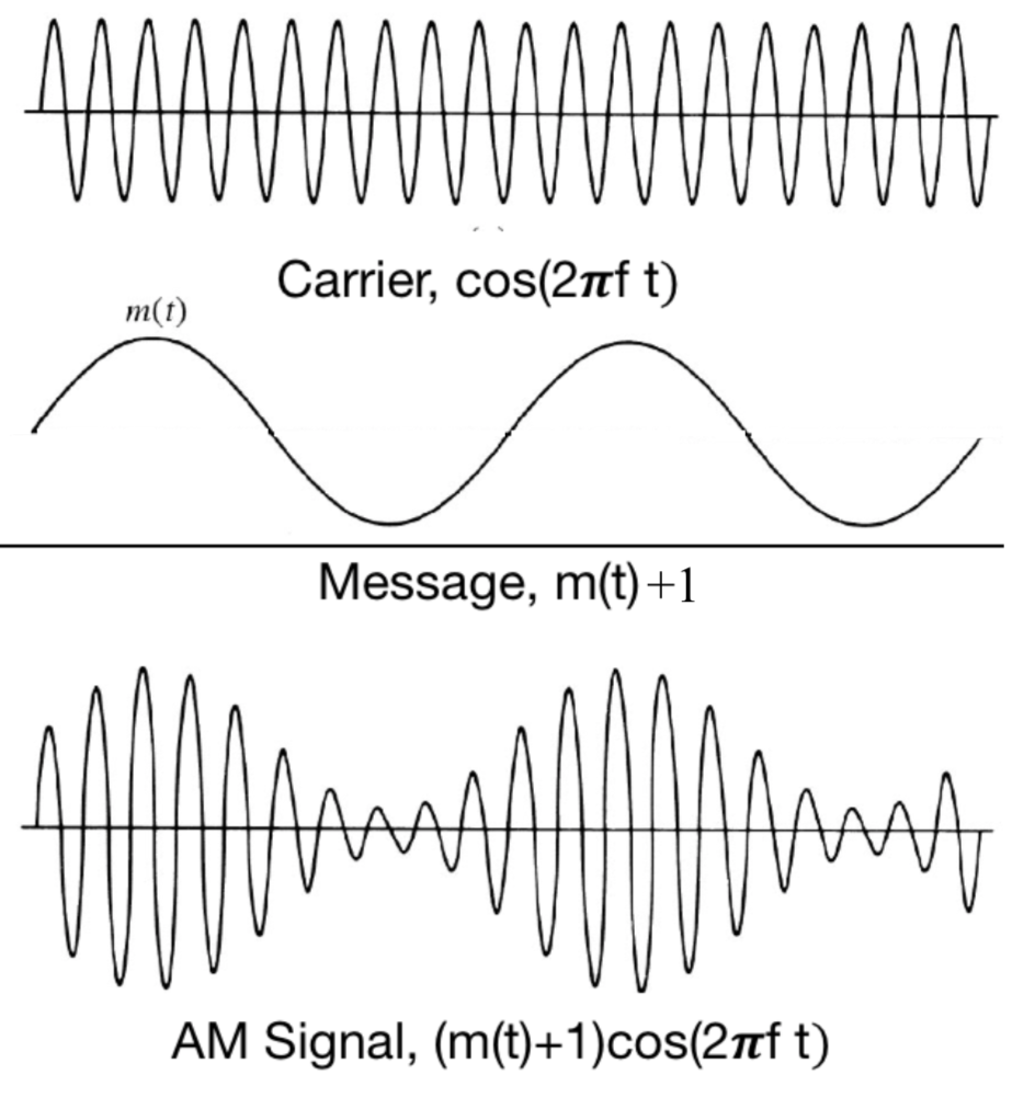
To do this we want a circuit that multiplies the two waves together. This can be accomplished with a FET that acts like a voltage-controlled variable resistor. You could do that with a jFET if the message were varying with a negative offset, ie VGS<0. Or you could do it with an nMOSFET if the message is varying with a positive offset. You have the flexibility to scale (reduce or amplify) and to offset your message signal anyway you want. The schematic above just shows a down-scaling.
To decide on this part of the circuit, look at the chapter on FETs where plots of ID vs VDS where shown for various values of VGS. This will help you select a choice of FET and an appropriately tuned message wave. Adjust the offsets and amplitudes of your carrier and message signals until you achieve the desired modulated waveform. The easiest way to cleanly trigger your oscilloscope is to hook your message up to one of the channels, and trigger on that channel. It will take some care to adjust the amplitude of the message wave so that it keeps the FET within its linear region. If that takes too long, you could proceed with a more simple approach where the message signal is just a bit stream, that completely turns the carrier on or off. Proceeding that way and then coming back to make a more analog signal variation, if time allows, is fine.
Amplification
It would be difficult to adjust the modulator circuit to match the voltage range needed for the LED, so we need to amplify it and apply an appropriate DC bias. LEDs have a minimum voltage requirement for turning on, so it's good to ensure you're above this. You could look up the required voltage in the LED datasheet, or just play around with it to measure it. Applying this DC offset is easy enough with a voltage divider and decoupling capacitor.Then you can hook up your LED; it should be bright enough to see by eye. (Make sure that the shorter end goes toward ground and you use a current limiting resistor to ground.) Since the light output of the LED is proportional to the current flowing through it, you can measure the voltage across the current limiting resistor (R6) as a proxy for the LED current, and hence the varying light intensity.
Before moving on to the next stages, make sure that these circuit stages are robust. For example, you should vary the frequency of both the carrier and message signals to make sure the circuit responds as expected. Then, fully document this with photos of the circuit and scopecaps of the waveforms. If you have trouble with getting the later stages to work, you should recheck the output of this stage and compare it to your logged waveforms.
Use the Openscope's FFT (Fast Fourier Transform) feature to get a view of the frequency spectrum of the transmitted signal. It should show that the message wave is in the side-band of the carrier frequency. Vary the message frequency a bit to see that in action.
Receiver
The receiver will extract the encoded signal. We will do that with a phototransistor with the output connected to the collector.When building your circuit, put the phototransistor right next to the LED, and push them together so that they are almost touching. This will create maximum signal strength so you can detect it easily even in a brightly lit room. Once you get the circuit working this way, you can try separating the LED and phototransistor and see if you can still detect the signal from a distance.
Ambient light will cause a DC offset in the received signal; you may also get 60Hz noise from the flickering of the room lights. Don't worry about this; if it's far from your message/carrier frequency we can filter it out later. (But if curious, you could check for this with the FFT feature.) To make it simple to begin with, you can cover the light path to block out stray light.
Amplifier
Your input signal at this point will likely be small, so to make things easier you can amplify it. Bigger is better in this case because we have a ~0.6 V diode drop to pay in the next stage, but adjust it to avoid hitting the rails. The amplifier in the circuit drawing above is just a generic symbol. You should figure out your own prefered way to get the signal conditioned how you want it, with appropriate AC coupling and DC bias if needed.
Filter
We're now ready to extract the signal. First you need to filter the specific frequency, ie tune the channel of your AM radio. You could do that with an LC resonator circuit, or more simply use a high-pass and low-pass filter together. Since you don't have conflicting information encoded by other transmitters at nearby frequencies, you can use a broad filtering band. In fact, only the high-pass is really required since the only other contribution is likely to be at 60 Hz. I suggest you start with just a high-pass filter and get the whole circuit working. Then go back and replace the filter stage with a bandpass filter only if you have time.
Rectifier
The diode rectifier cuts off the negative voltage swings with a half-wave rectifier, like you did at the beginning of the class. Then you use a capacitor (with a resistor to leak off the low frequency) to smooth away the carrier frequency and keep the message frequency.
With this, the circuit is complete! You could view the output on the openscope or drive your buzzer with it.
Going beyond
If you are motivated to go beyond the minimum requirements, there are several things that you could do with your circuit. Some ideas are listed below, but you are encouraged to try your own ideas to learn as much as you can.
- Once you have the circuit working with the LED and phototransistor placed very close together, try moving them apart to see if you can pick up a weaker signal. You might try coupling them together with a fiber optic cable for longer distance communication.
- Instead of using a 555 timer to send a boring square wave message, you could connect the microphone to an amplifier and use that as the message wave. Then you have a real, optically coupled radio.
- To send information in the message wave, you need to vary its amplitude. The simplest way to do that would be to use morse code to send simple on-off signals. Can you build a simple addition to the transmitter stages of your circuit that lets you send morse code? How could you visualize or vocalize the received morse code dots and dashes?
- Another way to encode signal information is by eclipsing the light path. You could try placing the LED and photoresistor a short distance apart and pass a pendulum between them. The period of the pendulum is a measure of the acceleration due to gravity, and the openscope can measure long timescales to give you that measure. Alternatively, you could set up the scope to trigger only when the signal gets blocked and measure the length of time that it is eclipsed. That would give you a measure of the speed of the pendulum. Once you get that working with a full eclipse, see if you can even detect a tiny dip in light from just the pendulum's string passing by.
- There has been a move recently to develop something called LiFi, which transmits network traffic by flashing the room lights at a high frequency. This won't work with incandescent or florescent bulbs, but LED lights are well matched to it. Flashing the lights at a few MHz would be unnoticed by the people in the room. (We don't notice the existing 60 Hz flashing.) Only a receiver similar to the one above would be sensitive. Google around to learn about LiFi. Your 555 timer is sending a boring stream of bits via LiFi in your circuit. To make this work across a room, however, you need to suppress the non-signal noise and get a large enough signal to be detected over a few meters. The frequency encoding is a powerful noise suppressor, but signal strength requires some care. See how far apart you can place the LED and photo-transistor and still get a detectable signal. To detect faint signals, you might have to tune the amplification as the signal size decreases.
- There is a story about cold-war era spies eavesdropping using an infrared laser. They bounced the (non-visible) laser off the window of an office. Sound waves in the office vibrated the window which modulated the reflected light received by a photodetector in a building across the street. This would be a tiny signal, so modulation with a high-frequency carrier wave is required to make the signal detectable over noise. Don't try this for eavesdropping, for legal reasons, but maybe you could approximate it by placing the LED and phototransistor near a window, with the direct path between them blocked. Can you see the signal modulate as you cause the window to vibrate by singing? It would be hard to amplify that enough to hear it on the buzzer, but you might be able to "see" the signal by connecting an openscope channel to the output of your circuit. (Note that in this case you would directly connect the carrier wave to the LED without a message wave modulation--the varying reflection is what would cause the modulation.)