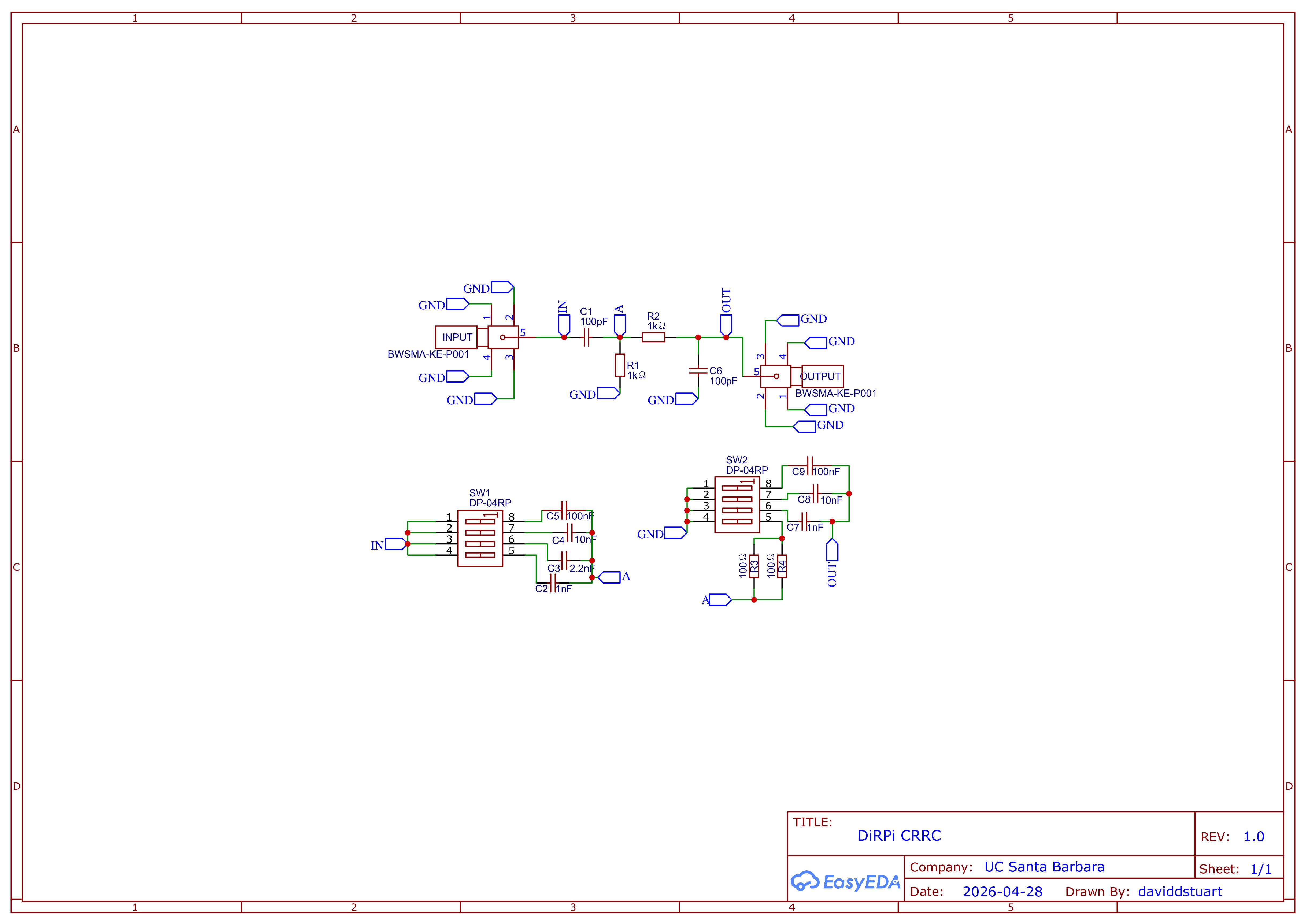
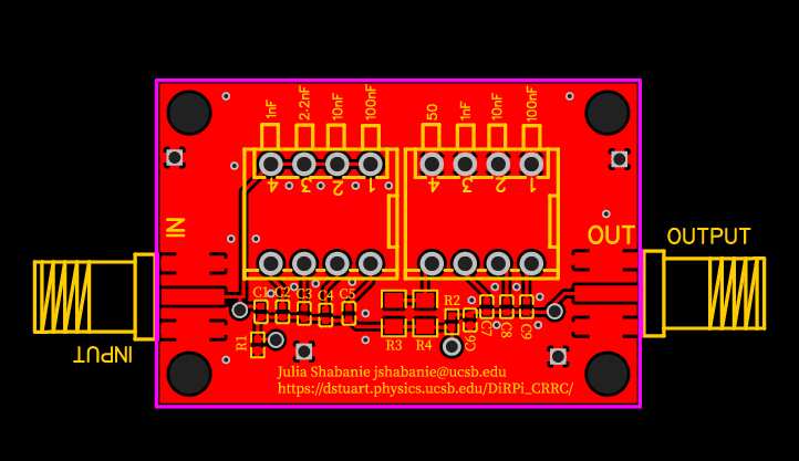
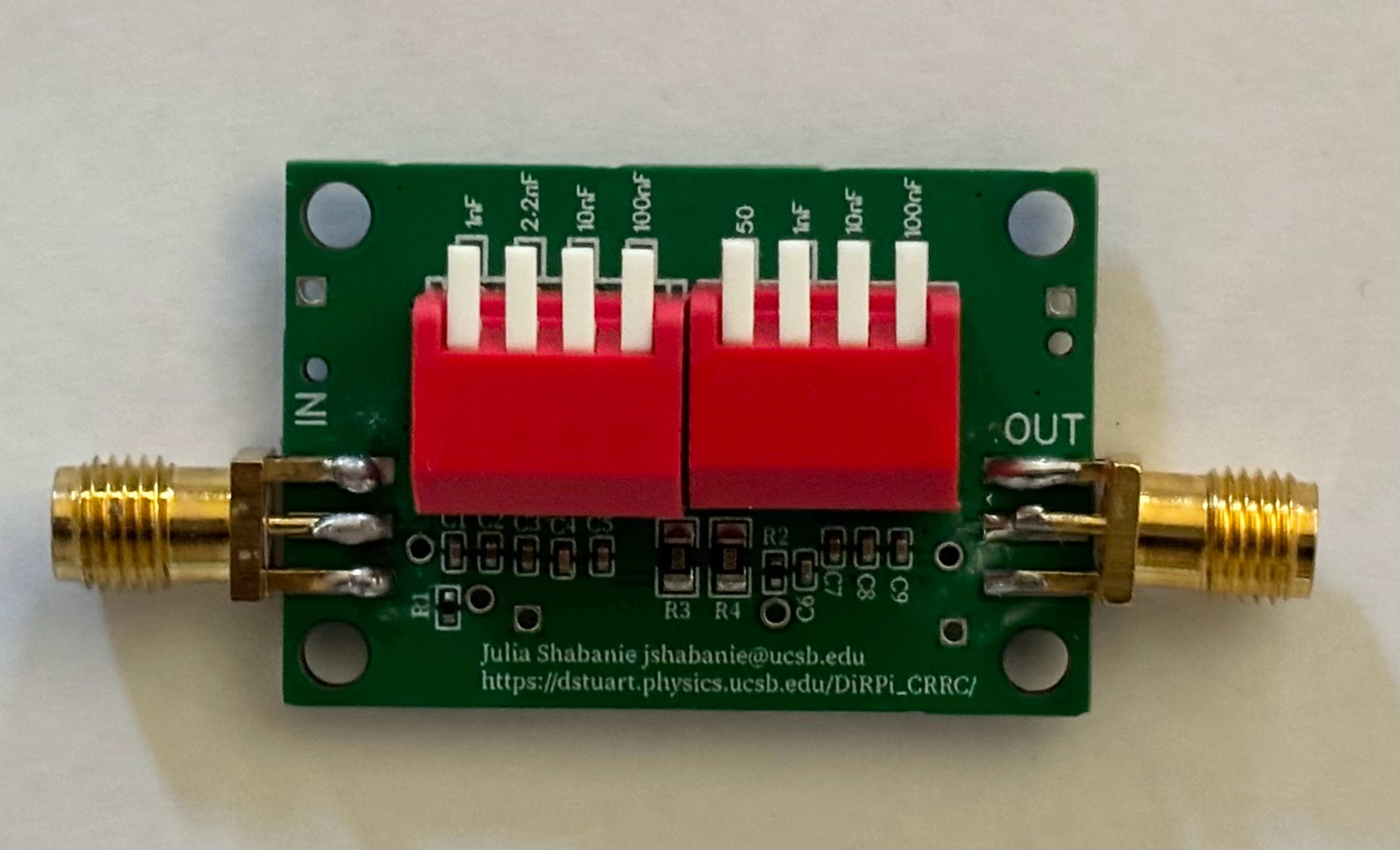
This CRRC circuit utilizes a high pass filter followed by a low pass filter to shape the input pulse seen by a muon entering/passing through a slab detector, in order for a DiRPi or other circuits to read the pulse despite limitations in sampling speed. The piano key switches added to the basic CRRC configuration allow the user to control the RC values by adding capacitors in parallel, therefore enabling the user to manipulate the pulse shape to fit their design needs. Also available is one switch which may add 50 Ω in parallel to the resistor of the low pass filter, if desired.
We consider the response of a passive bandpass filter to a rectangular pulse in the time domain (a rectangular pulse generated as a positive step function for the rising edge and a negative step function as the falling edge of the pulse). The muon pulse happens very quickly and acts as an impulse (Dirac) function, and may often be missed by the device to which it is an input if the sampling rate is much larger than the duration of the pulse (DiRPi has a sample rate of 25 ns). Solving this issue is the central purpose of the circuit: the switches allow the user to stretch the output pulse width until it comfortably spans one or more full sample periods of the readout system, dramatically reducing the probability that the pulse peak falls between two samples and is missed or underestimated. The high pass stage (the first CR) contains a series capacitor which eliminates the static DC offset or baseline noise that may be present. The low pass stage (the second RC) contains a parallel capacitor and attenuates high frequencies, rounding off the sharp pulse into a smoother and wider curve.
Each set of piano key switches selects additional capacitors to be placed in parallel with the existing stage capacitors, increasing the effective capacitance and therefore increasing the RC time constant of that stage of the filter. Because the shaping time constant τ = RC directly sets both the rise time and the width of the shaped output pulse, toggling the switches stretches the pulse in time.
For the high-pass (CR) stage, adding capacitance increases τ1 = R2C1, which lengthens the rise time of the shaped pulse and shifts the high-pass cutoff frequency downward. For the low-pass (RC) stage, adding capacitance increases τ2 = R1C6, which widens and rounds the trailing edge of the pulse further and shifts the low-pass cutoff frequency downward. When τ1 = τ2 the filter produces a true CR-RC shape whose output is a symmetric, almost-normal (Gaussian) pulse. When the two time constants differ, the pulse becomes asymmetric, with a faster rise or a slower fall, depending on which stage has the dominant constant.
The optional 50 Ω resistor that may be added in parallel with R1 of the low-pass stage reduces the effective resistance of that stage, lowering τ2 and sharpening response to the falling edge (negative input) of the pulse input.
The available capacitor steps (1 nF, 2.2 nF, 10 nF, 100 nF in parallel for the CR, and 1 nF, 10 nF, 100 nF for the RC) provide a wide range of options, allowing the same board to be adapted to readout systems with different sampling rates or to signals with different pulse widths.
The high pass cutoff frequency can be calculated using 1/(2π·RC) where RC are the values of the first capacitor and resistor, while the low pass cutoff frequency can be calculated using 1/(2π·RC) where RC are the values of the second capacitor and resistor.
Note: SMA connectors have been soldered on by hand due to manufacturing issues.
Using a 5 kHz, 1 Vpp pulse with width 13 µs and 1 µs edge time (chose higher pulse width due to unreliable behavior of oscilloscope at nanosecond pulse width).
High-Pass Stage
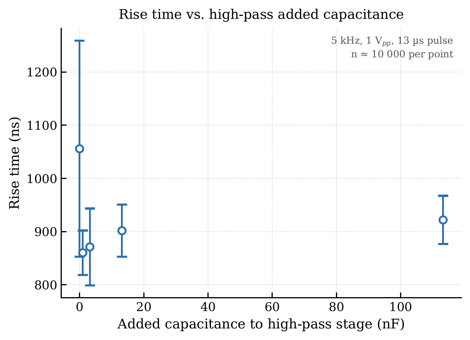
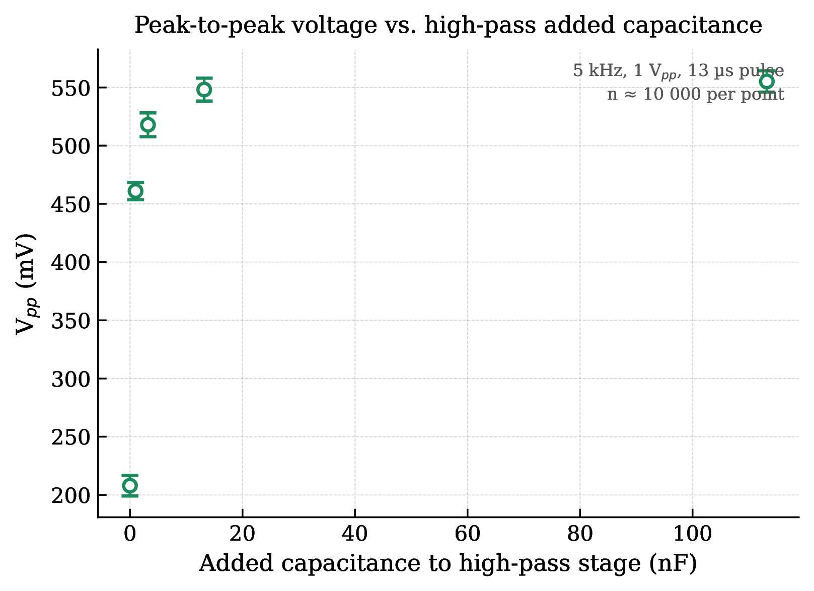
Adding capacitance to the high pass produces a sharp jump in Vpp from ~208 mV (baseline) up to ~555 mV at 113.2 nF, which is more than a 2.5x gain. Rise time actually decreases slightly from baseline (~1056 ns) when you add the first 1 nF, then climbs back gradually as more capacitance is added. The baseline standard dev on rise time is notably large (±203 ns), suggesting the unfiltered pulse is noisy or that the 25 ns sampling rate is reading the edge at different spots.
Low-Pass Stage
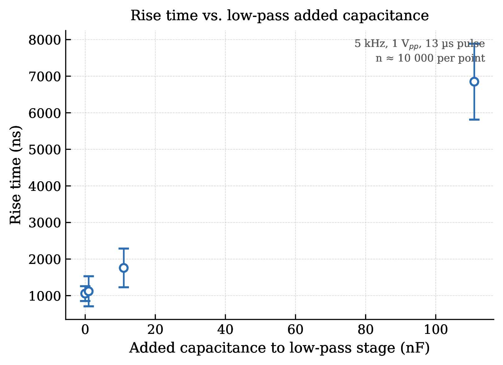
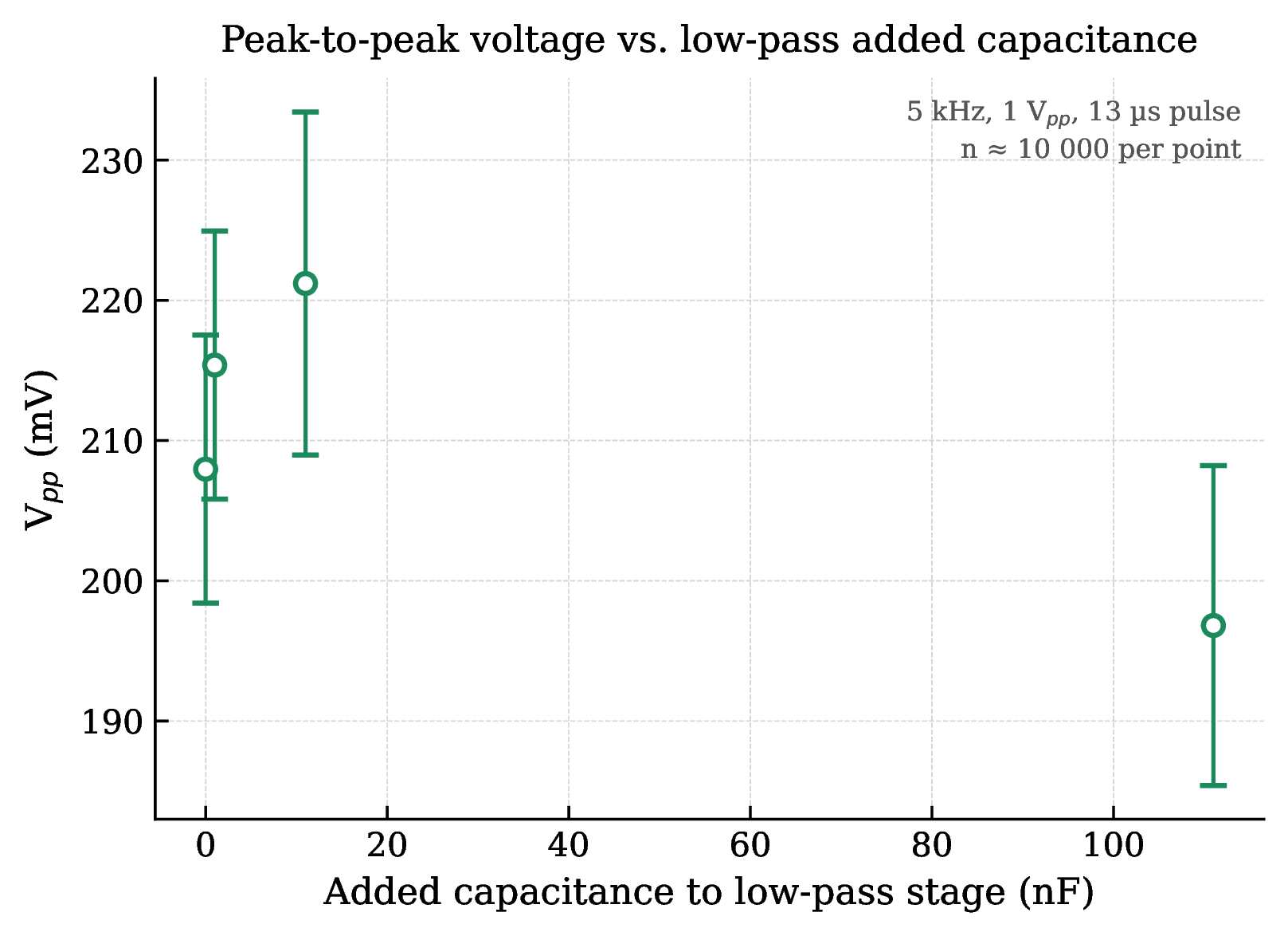
Adding capacitance to the low pass stage causes dramatic pulse stretching. Rise time scales from ~1056 ns at baseline to ~6850 ns with 111 nF added (nearly 7x wider) with the standard deviation also growing substantially (±1039 ns). Meanwhile, Vpp barely changes (196–221 mV), confirming that the low-pass stage mostly reshapes the pulse in time without significantly attenuating amplitude.